78+120+78m预应力混凝土连续梁桥主跨桥设计(含CAD图)(任务书,开题报告,外文翻译,论文计算书22000字,CAD图20张)
摘要
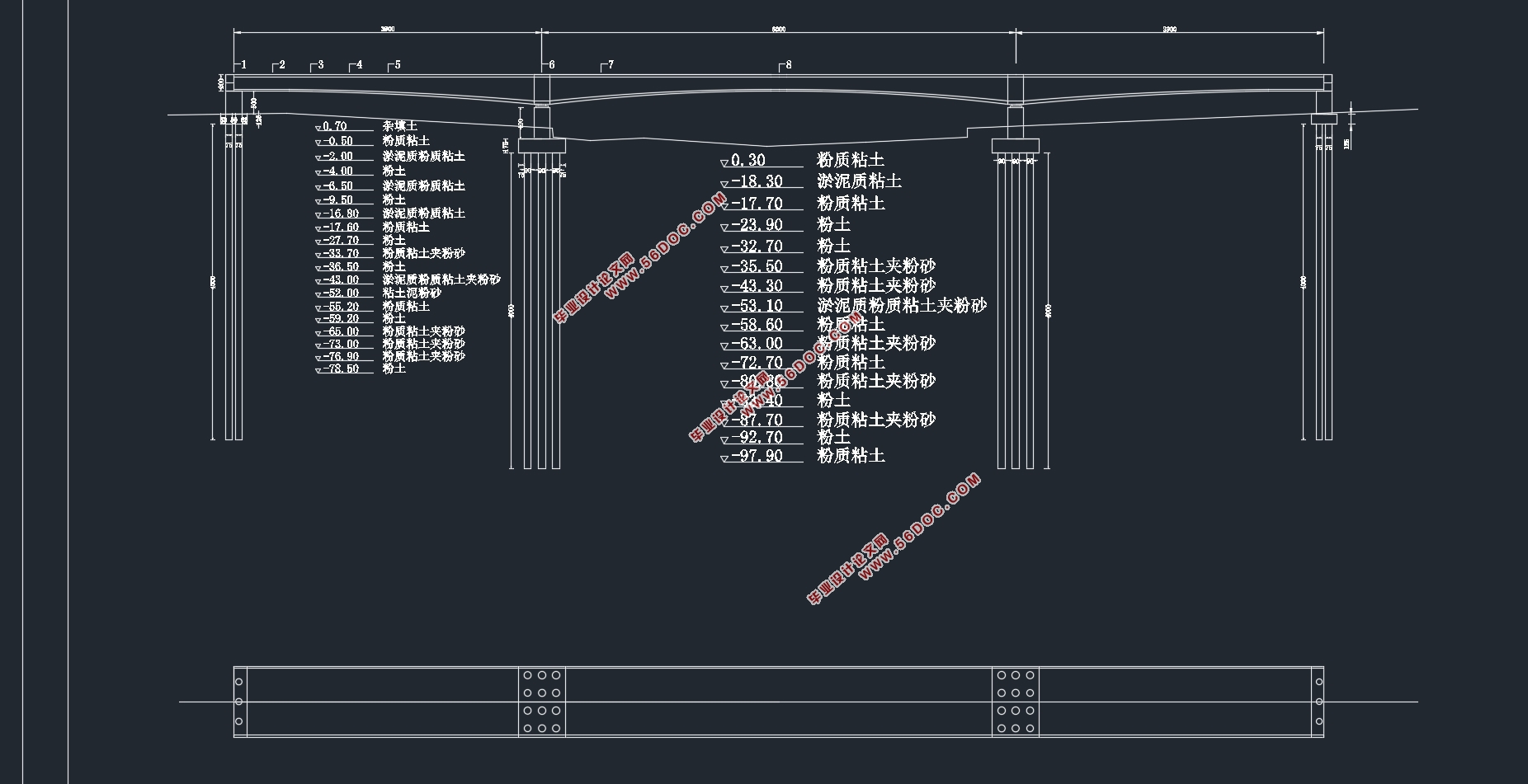
近年来,预应力混凝土连续梁桥由于其跨越能力大、施工方法灵活、适应性强、结构刚度大、抗地震能力强、通车平顺性好以及造型美观等特点,在国内越来越得到广泛的应用。本论文设计的是八坼运河预应力混凝土连续梁桥主跨桥方案设计,大桥位于吴江市八坼镇境内,为东西向跨越京杭大运河桥梁。由于苏南运河航道整治,全线要求达到Ⅲ级航道标准,要求通航净空满足80×7m要求。老桥通航净宽不满足80m要求,需拆除重建。考虑未来吴江市城市主干线东西干线的顺接通行要求,将新建桥梁桥位北移约2km,并提高原有桥梁设计标准重建。未来八坼桥梁规划桥宽为双幅共36m,现阶段实施单幅18m,现阶段实施桥梁采用双向4车道机非混行车道,路线线形设计预留100km/h时速标准,两侧设置防撞护栏。为了满足Ⅲ级航道的要求连续梁桥的主跨要大于95~100m,主桥拟采用三跨连续梁桥。本桥主跨采用78+120+78m预应力混凝土变截面连续箱梁。
设计主要过程如下:
1. 首先进行恒载、活载及次内力的计算,在此基础上进行荷载组合,绘制弯矩和剪力包络图。
2.根据短期效应组合估算纵向预应力筋数量,然后再布置预应力钢束和预应力损失的计算。
3.进行截面强度验算。
关键词:设计 连续梁桥 预应力
Abstract
In recent years, prestressed concrete continuous beam bridge because of its ability to span large、flexible construction methods、Adaptability、structural rigidity、 anti-seismic capability, as well as the opening of a good ride beautiful shape and other characteristics,In the country it has been more widely used. In this thesis, the canal is Bache prestressed concrete continuous beam bridge main span of the bridge design, Bache Wujiang Bridge is located within the town, East-west across the Grand Canal bridge. As Sunan Canal waterway, full range of requirements to achieve Grade Ⅲ standard, requiring navigation clearance requirements to meet the 80 × 7m. Old Bridge navigable clear width 80m requirement is not satisfied, to be demolished and rebuilt. Consider the future Wujiang City trunk line connected to something along the lines of requirements, the new bridge bridge-bit northward approximately 2km, and improve the existing bridge design standards reconstruction. Future planning Bache bridge bridge width is double width of 36m, single-stage implementation of 18m, the implementation stage, two-way four-lane bridge machine immiscible carriageway route alignment design reserved 100km/h speed standard, crash barriers on both sides. In order to meet the requirements of Grade Ⅲ continuous bridge main span is greater than 95 ~ 100m, the main bridge intends to adopt three-span continuous beam bridge. The main span of the bridge using 78 +120 +78 m uniform continuous prestressed concrete box girder.
Design of the main process is as follows:
First, the constant load, live load class times force calculations performed on the basis of load combinations, draw bending moment and shear envelope.
Second,Short-term effects of a combination according to estimates the number of longitudinal prestressing tendons, and then arranged and prestressed tendon damage calculations.
Thirdly,Conduct cross-sectional strength checking.
Key Words: design; continuous bridge; prestress
1.1工程概况与背景
八坼运河大桥位于吴江市八坼镇境内,为东西向跨越京杭大运河桥梁。由于苏南运河航道整治,全线要求达到Ⅲ级航道标准,要求通航净空满足80×7m要求。老桥通航净宽不满足80m要求,需拆除重建。考虑未来吴江市城市主干线东西干线的顺接通行要求,将新建桥梁桥位北移约2km,并提高原有桥梁设计标准重建。未来八坼桥梁规划桥宽为双幅共36m,现阶段实施单幅18m,现阶段实施桥梁采用双向4车道机非混行车道,路线线形设计预留100km/h时速标准,两侧设置防撞护栏。


目录
摘要 I
Abstract II
绪论 1
第一章 设计原始资料 4
1.1工程概况与背景 4
1.2水文地质资料及设计依据 5
1.2.1桥位地形图和地质资料 5
1.2.2采用的主要设计标准与规范 6
1.2.3主要技术标准和设计基础资料 7
第二章 方案选择 9
2.1所选方案为变截面预应力混凝土连续梁桥 9
2.2变截面预应力混凝土连续梁桥的特点 9
第三章 桥跨总体布置及结构尺寸拟定 10
3.1桥梁总体布置 10
3.2桥孔分跨 10
3.3截面形式 10
3.3.1立截面 10
3.3.2横截面 11
3.3.3上部结构尺寸拟定 12
第四章 荷载内力计算 15
4.1恒载内力计算 15
4.1.1第一期恒载(结构自重) 15
4.1.2第二期恒载(桥面二期荷载) 15
4.2活载内力计算 15
4.3支座位移引起的内力计算 16
4.4荷载组合及内力包络图 16
第五章 次内力计算 23
5.1温差应力计算 23
5.2支座沉降引起的次内力计算 24
第六章 内力组合 25
6.1作用和作用效应 25
6.2承载能力极限状态下的效应组合 25
6.3正常使用极限状态下的效应组合 28
6.3.1作用短期效应组合 28
6.3.2作用长期效应组合 29
第七章 预应力钢束的估算与布置 31
7.1按承载能力极限计算时满足正截面强度要求 31
7.3预应力钢束的布置(具体布置图见图纸) 38
第八章 预应力损失计算 40
8.1预应力损失的计算 40
8.1.1摩阻损失 40
8.1.2锚具变形损失 41
8.1.3混凝土的弹性压缩 43
8.1.4钢束松弛损失 44
8.1.5混凝土收缩、徐变损失 46
8.1.6有效预应力的计算 47
第九章 截面强度验算 49
9.1基本理论 49
9.2按构件承载能力极限状态计算 49
9.3正常使用极限状态计算 52
9.3.1正截面抗裂验算 53
9.3.2斜截面抗裂验算 54
9.3.3持久状况的应力验算 58
9.4 预应力筋拉应力验算 60
第十章 墩及桩基础设计与计算 61
10.1支座 61
10.2桩基础设计 61
参考文献 63
总结与展望 64
致谢 65
|


