某高层商住楼建筑给排水设计(含CAD图)(任务书,开题报告,外文翻译,计算说明书20000字,CAD图纸14张)
摘 要
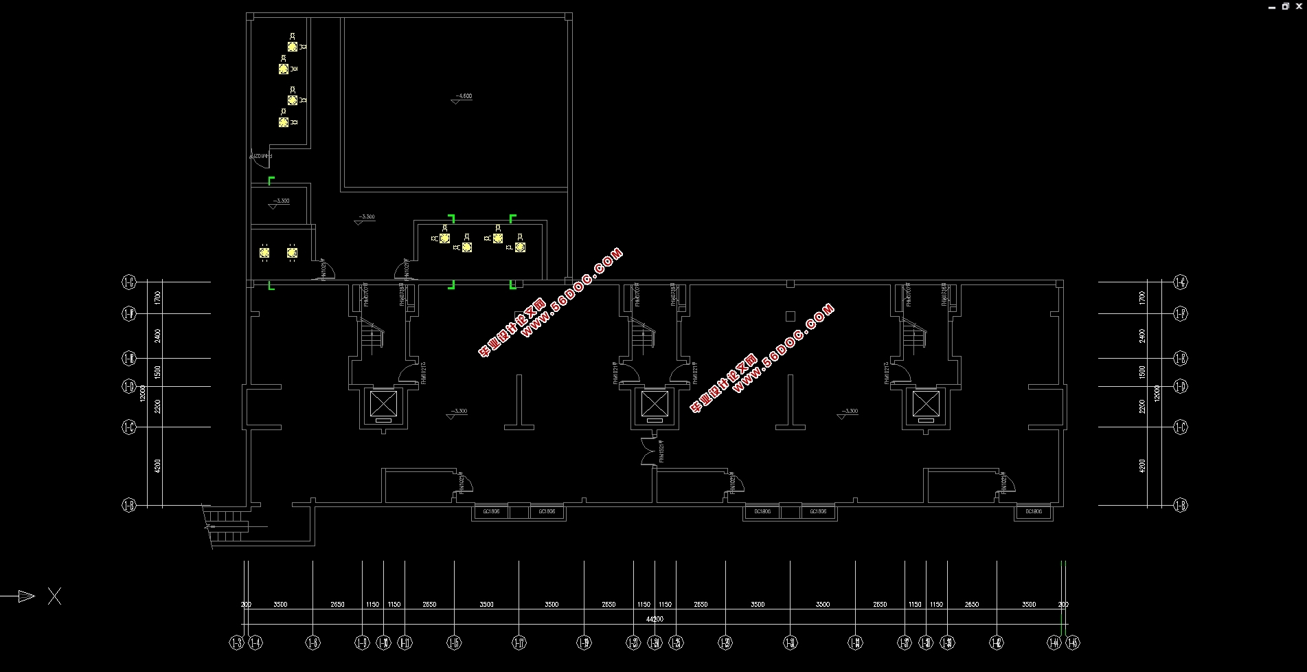
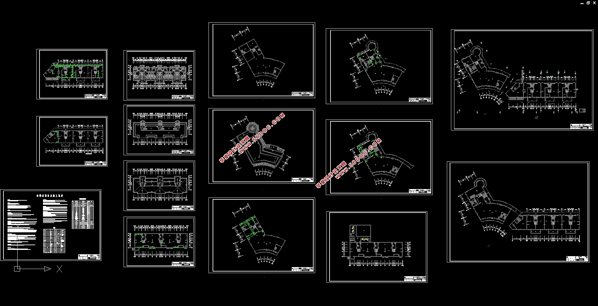
本次设计为某高层商住楼建筑给排水设计,主要包括生活给水系统、消火栓给水系统、自动喷水灭火系统、生活排水系统和建筑雨水排水系统五个系统。
给水系统采用竖向分区,1到2层为低区,由市政管网直接供水;3层到11层为高区,采用变频加压供水。采用上行下给的供水方式,由变频调速泵直接向高区管网供水;室内生活给水管管材选用塑料管。
建筑室内排水采用污、废水合流制,室外排水采用雨、污分流制。室内±0.000以上污废水重力自流排入室外污水管,地下室污废水采用潜污泵提升至室外污水管,排水立管主要采用伸顶通气方式和专用通气立管通气方式,部分立管需侧墙通气,排水管采用排水专用塑料管;屋面雨水采用重力流雨水斗,外排引向室外雨水管网。雨水管采用U-PVC管。
根据规范,本建筑为商住楼,属二类建筑,火灾危险等级为中危I级,负一层地下车库为中危Ⅱ级。消火栓系统、自动喷水灭火系统不分区,消火栓管材采用普通镀锌钢管、喷淋管材采用热镀锌钢管。
关键词:给水系统;排水系统;消防系统;自喷系统。
Water supply and drainage design for a high-rise residential building
Abstract
This design is for a high-rise commercial building water supply and drainage design, mainly including domestic water supply system, hydrant water supply system, automatic sprinkler system, domestic drainage system and building rainwater drainage system five systems.
The water supply system is divided into vertical zones, and the first and second floors are low zones, which are directly supplied by the municipal pipe network. Floors 3 to 11 are high, with variable frequency pressurized water supply. The water supply is up and down, and the inverter speed regulating pump supplies water directly to the high area pipe network. Indoor life gives conduit material to choose plastic pipe.
The indoor drainage of the building adopts the combined system of sewage and waste water, and the outdoor drainage adopts the separate system of rain and sewage. More than ±0.000 indoor gravity waste water gravity discharged into the outdoor sewer, underground sewage and sewage using a submersible sewage pump to the outdoor sewage pipe, drainage riser mainly adopts ceiling ventilation and special ventilation riser ventilation, some of the riser requires side wall Ventilation, The drainage pipe adopts the special plastic pipe for drainage; rain on the roof using gravity flow rainwater bucket, outside the drainage line to the outdoor rainwater pipe network. The rain water pipe uses U-PVC pipe.
According to the specification, the architecture for the mass, belongs to the second building, fire danger rating for dangerous grade I, in the negative a layer of underground garage for dangerous Ⅱ level. Fire hydrant system, automatic sprinkler system is not divided, fire hydrant pipe use common galvanized steel pipe, spray pipe use hot dip galvanized steel pipe.
Keywords: water supply system; Drainage system; Fire protection system; Flowing system.
目录
第一部分 设计方案比选 1
第一章 建筑给水系统 1
1.1.1给水方式选择原则 1
1.1.2给水方式的选择 1
第二章 建筑排水系统 2
1.2.1排水系统的基本组成和要求 2
1.2.2排水系统的类型 2
1.2.3排水系统的选择 3
第三章 建筑消防系统 3
1.3.1消火栓系统给水方式的选择 3
1.3.2、自动喷水灭火系统的初步确定 4
第四章 雨水排水系统 4
第二部分 设计方案说明 5
第一章 给水工程 5
第二章 排水工程 5
第三章 消防给水 5
第四章 管道的平面布置及管材 6
第三部分 设计计算 7
第一章 室内给水系统的计算 7
3.1.1给水用水定额及时变化系数 7
3.1.2最高日用水量 7
3.1.3最高日最大时用水量 7
3.1.4生活给水管道水头损失计算依据 8
3.1.5设计秒流量 8
3.1.6增压设备 17
3.1.7地下室内贮水池容积 18
3.1.8减压设备 19
第二章 室内消火栓给水系统的计算 20
3.2.1消火栓的布置 20
3.2.2水枪喷嘴处所需的水压 20
3.2.3水枪喷嘴的出流量 21
3.2.4水带阻力 21
3.2.5消火栓口所需水压 21
3.2.6消火栓减压计算 26
3.2.7水泵接合器 28
3.2.8消防水箱 28
3.2.9消防贮水池 30
3.2.10室外消火栓布置 30
第三章 自动喷水灭火系统的计算 32
3.3.1自动喷淋灭火系统的基本参数 32
3.3.2管道与报警阀布置 32
3.3.3喷淋的选用与布置 33
3.3.4喷头的布置间距 33
3.3.5系统的设计流量 34
3.3.6各个防火分区水力计算 34
3.3.7校核 40
3.3.8增压设备 41
3.3.9喷淋减压孔板计算 42
第四章 建筑内部排水系统的计算 44
3.4.1计算公式及参数 44
3.4.2排水支管和横干管的计算 44
3.4.3立管计算 48
3.4.4排水横干管的计算 48
3.4.5通气立管的计算 49
3.4.6污水提升 49
3.4.7化粪池的计算 49
第五章 建筑雨水排水系统的计算 52
3.5.1屋面雨水排水系统的分类 52
3.5.2屋面雨水排水系统的组成 52
3.5.3管道的布置与敷设 52
3.5.4设计暴雨强度 53
3.5.5汇水面积 53
3.5.6立管布置及汇水面积的划分 53
3.5.7雨水量计算 54
3.5.8管材计算及选用 55
结论 56
参考文献 57
致谢 58
|