江苏泗洪县某镇给水工程设计(含CAD图)(任务书,开题报告,外文翻译,计算说明书40000字,CAD图9张)
摘 要
该给水工程设计主要包括市政给水管网和净水厂工艺设计两部分。其中市政给水管网是以远期最高日最大时用水量约11.5万吨/天设计的,净水厂工艺是以近期日产水量约4.3万吨/天设计的。
市政给水管网采用环状和枝状管网的相互结合的方式供水至用户,以确保供水可靠性和安全性。根据不同性质地块不同的用水定额,计算得到集中流量和沿线流量。沿线流量按配水管段的供水面积分配计算,集中流量则分配到所处节点上。管段流量经过初分配、平差、工况下水力计算,确定供水最不利点。二泵站的供水流量为1333.808L/s,供水扬程为42m。同时管网的设计应经过事故工况、消防工况条件下的校核,以满足用户对供水流量、水压的要求。
净水厂水处理采用“预氧化——絮凝——沉淀——过滤——活性炭吸附——消毒”的工艺流程。原水由取水泵房通过输水管线输送至净水厂的配水井。此时的浑水中加入混凝剂依次通过网格絮凝池、平流沉淀池、V型滤池、活性炭吸附滤池,再用液氯消毒进入清水池。最终清水池中的自来水经过二泵房加压输送至市政给水管网。
关键词:给水管网 集中流量 沿线流量 最不利点 净水厂水处理工艺 混凝剂液氯
Design of Water supply engineering in shuanggou town, Sihong county
Abstract
The design of water supply engineering mainly includes the municipal water supply pipeline network and the water treatment process design.The municipal water supply pipe network is designed according to the maximum daily maximum hour water consumption of about 115000 tons every day, water treatment process is designed according to the recent average daily output of about 43000 tons every day.
In order to ensure water supply reliability and security, municipal water supply pipe network consists of pipe network and branched network supplying water to the user in this town. According to the different water consumption of different parcels’ nature, we can calculate to get the concentration flow and along the line flow.Along the line flow is distributed according to match the distribution area, concentrated flow is distributed nearby to the node. The flow through the initial allocation, adjustment, hydraulic analysis and calculation in working condition determines the most unfavorable point of water supply network. The design water flow rate of secondary pump station is 1333.808 L/s, water head of delivery is 42 m. At the same time, pipe network design has been checked in accident condition and fire condition to meet user demand for water flow rate and pressure.
Water treatment method in water treatment works will use "pre-oxidation, flocculation, sedimentation, filtration, activated carbon adsorption, disinfection” process. Raw water is acquired by the water pump room and carried with the water pipeline conveying to match well. At this time, the muddy water with coagulant in turn goes by the grid flocculation tank, horizontal flow sedimentation tank, V filter, activated carbon adsorption tank with chlorine disinfection into clear-water reservoir. Eventually the tap water in clear water reservoir is pressured to municipal water supply pipe network by secondary pump.
Keywords: water supply pipe network, the concentration flow, along the line flow, the most unfavorable point, water treatment works water treatment process, coagulant, liquid chlorine
1.1 给水工程规划用水量指标:
居住区用水 90m3/d•ha
市政、公用设施用水 20 m3/d•ha
道路、广场用水 15 m3/d•ha
绿地用水 15 m3/d•ha
行政办公用水 50 m3/d•ha
商业金融用水 40 m3/d•ha
体育、文化、娱乐用水 40 m3/d•ha
医疗卫生用水 40 m3/d•ha
教育、科研设计用水 40 m3/d•ha
其它公用设施用水 40 m3/d•ha
工业用水 120 m3/d•ha
目 录
第一章 给水工程给水管网设计 6
1.1 给水工程规划用水量指标 6
1.2 最高日设计用水量的计算 6
1.2.1城市最高日综合生活用水量 7
1.2.2 工业最高日用水量 7
1.2.3其他用水量及漏水量 7
1.2.4消防用水量 7
1.2.5最高日设计用水量 7
1.2.6 最高日最高时用水量 9
1.2.7 清水池容积设计 9
1.3给水管网定线 10
1.3.1 管网布置形式 10
1.3.2确定自来水厂位置 10
1.3.3 官网定线 10
1.3.4输水管定线 10
1.4设计流量分配与管径设计 11
1.4.1节点流量分配计算 11
1.4.2管段设计流量分配 13
1.4.3实际方案分析 13
1.5设计工况水力分析 15
1.6泵站扬程设计 17
1.7事故工况校核 18
1.8消防工况校核 21
第二章 给水工程净水厂设计计算 25
2.1 配水井 25
2.1.1进水管管径 25
2.1.2 出水管管径 25
2.1.3 进水井直径 25
2.1.4 堰上水头 25
2.1.5 出水井直径 26
2.1.6 配水井高度 26
2.2 混凝设施 26
2.2.1药剂溶解及溶液配制 26
2.2.2 投药管 28
2.2.3 溶解池搅拌设备 29
2.2.4 计量投加设备 29
2.2.5 仓库 30
2.2.6 混合设备设计计算 31
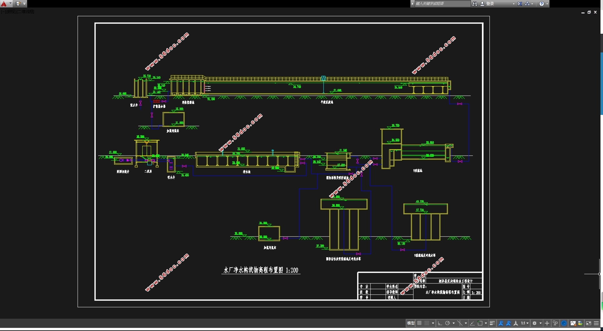
2.3 网格(栅条)絮凝池设计计算 32
2.3.1设计计算 32
2.3.2水头损失 35
2.3.3各段的停留时间 35
2.3.4速度梯度 35
2.3.5 排泥系统 36
2.4平沉淀池流 37
2.4.1 设计计算 37
2.4.2沉淀池尺寸计算 37
2.4.3沉淀池的进水设计 38
2.4.4沉淀池集水系统 38
2.4.5沉淀池排泥系统 40
2.5 V型滤池 41
2.5.1设计计算 42
2.5.2滤池平面尺寸计算 42
2.5.3反冲洗管渠系统 44
2.5.4 滤池管渠的布置 46
2.5.5 反冲洗水的供给(选用冲洗水箱供水的计算) 49
2.5.6反洗空气的供给 51
2.6 活性炭滤池的设计计算 53
2.6.1滤池面积及尺寸 53
2.6.2每格滤池的配水系统 54
2.6.3 滤池的各种管渠计算 56
2.6.4反冲洗高位水箱 57
2.7 消毒 57
2.7.1加氯量计算 57
2.7.2储氯量计算 57
2.7.3加氯间、氯库 58
2.8 清水池设计 58
2.8.1清水池的有效容积 58
2.8.2管道系统 59
2.8.3 清水池的布置 60
2.9 吸水井设计 60
2.9.1吸水井布置要求 60
2.9.2吸水井尺寸计算 61
2.10 二级泵房设计 61
2.10.1设计水量 62
2.10.2水泵选型 62
2.10.3二级泵站泵房尺寸设计 62
2.10.4泵的最大安装高度Hs 66
2.10.5选择起重设备型号 67
2.10.6选择真空泵、排水泵等附属设备 67
2.10.7泵站的平面布置,泵房的平面尺寸 67
第三章 给水工程净水厂设计说明 67
3.1城镇概况 69
3.1.1自然条件 69
3.1.2水源状况 69
3.2 工程设计 69
3.2.1设计任务 69
3.2.2 设计内容 70
3.2.3设计图纸 70
3.2.4主要参考资料及编制依据 70
3.3 设计水量、规模和流程 71
3.3.1设计水质 71
3.3.2设计水量 72
3.3.3给水处理厂的设计规模 72
3.3.4处理工艺流程的选择 72
3.3.5水处理工艺的确定 73
3.4药剂选择及投加方式 73
3.4.1 预氧化剂选择 73
3.4.2混凝剂 74
3.4.3消毒剂 76
3.5水处理构筑物的选择 77
3.5.1混合设施 77
3.5.2絮凝 78
3.5.3沉淀 79
3.5.4 过滤 80
3.5.5活性炭吸附 82
3.6给水厂净水构筑物的说明 83
3.6.1混凝设施 83
3.6.2扩散混合器 84
3.6.3网格(栅条)絮凝池 85
3.6.4平流沉淀池 86
3.6.5 V型滤池 89
3.6.6加氯间 92
3.6.7清水池 93
3.6.8吸水井 94
3.6.9二级泵房 94
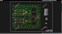
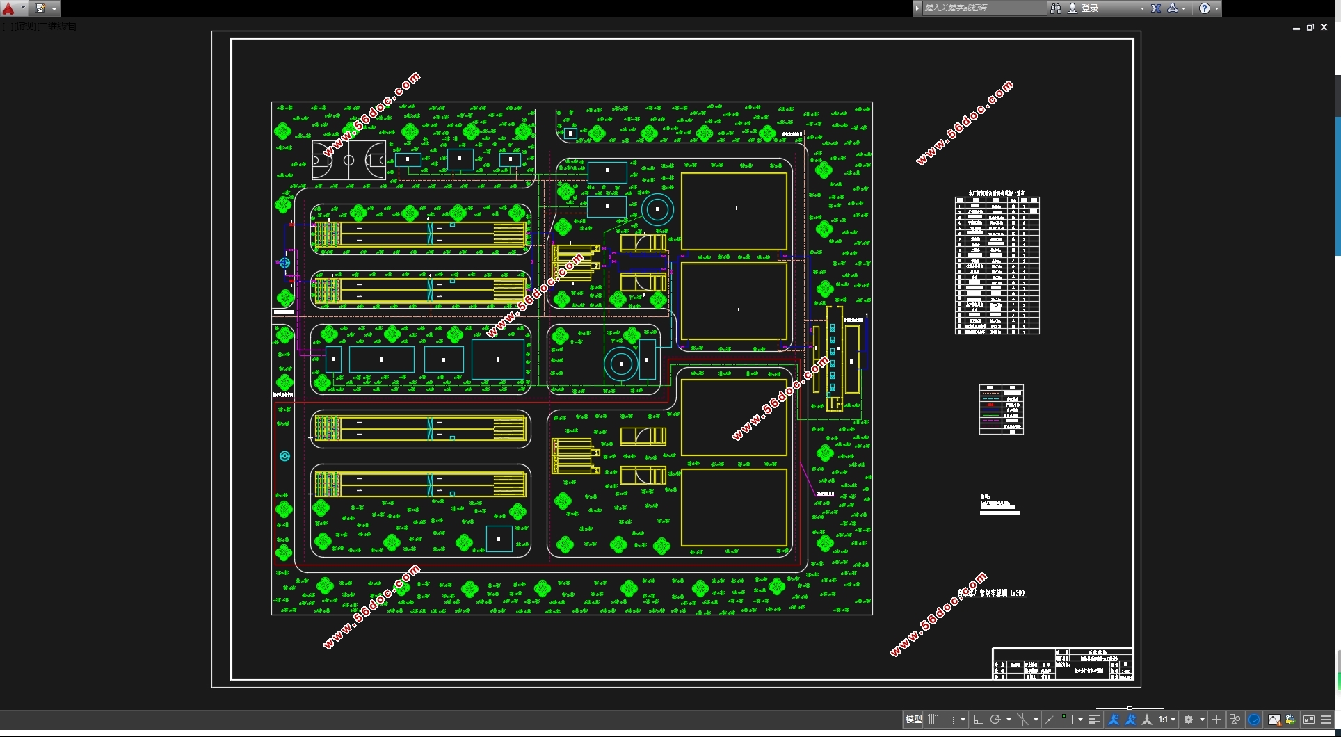
3.7给水厂平面和高程布置 95
3.7.1 给水厂平面布置 96
3.7.2给水厂高程布置 98
参考文献 102
结语 103
致谢 104
|