Can总线通信研究与硬件设计
来源:56doc.com 资料编号:5D11002 资料等级:★★★★★ %E8%B5%84%E6%96%99%E7%BC%96%E5%8F%B7%EF%BC%9A5D11002

资料介绍
Can总线通信研究与硬件设计(毕业论文15000字,外文翻译)
摘 要
CAN总线是控制器局域网总线(Controller Area Network)的简称。属于现场总线的范畴,是一种有效支持分布式控制或实时控制的串行通信网络。CAN总线是一种多主方式的串行通讯总线,是国际上应用最广泛的现场总线之一,现已被应用到各个自动化控制系统中,从高速的网络到低价位的多路接线都可以使用CAN总线。CAN总线是一种全双工通信的串行通信网络,属于现场总线的一种,它的数据通信功能强大,能够有效的支持分布式控制或实时控制系统。相比与其它现场总线,CAN总线具有通信快、效率高、易实现、可靠性高等优势,现在已经在很多领域中都得到了应用。本文重点就基于单片机的CAN总线通信设计的实现进行介绍,通过CAN控制器以及CAN收发器把串口发送来的数据转换成CAN通信的数据,然后又把数据转换成串口通信数据回发给计算机,实现数据的自发自收。
关键词 CAN总线;通信;现场总线
CAN bus communication research and hardware design
Abstract
CAN bus is the Controller LAN bus (Controller Area Network). Belongs to the category of the fieldbus, and is an effective support distributed control or real-time control of serial communication network. CAN bus is a main way of serial communication bus, is one of the most widely used field bus in the world, has now been applied to various automation control system, from the network to the low price of multiplex wiring CAN bus CAN be used. CAN bus is a full-duplex communication serial communication network, belongs to a kind of fieldbus, it has powerful data communication function, CAN effectively support distributed control or real-time control system. Compared with other field bus, CAN bus communication is fast, high efficiency, easy realize and high reliability advantages, now has been applied in many fields. This paper is based on single chip microcomputer, introduces the implementation of the CAN bus communication design through the CAN controller and CAN transceiver to a serial port to send data into the CAN communication data, and then send data into the serial communications data back to the computer, realizing data of spontaneous.
Key words CAN bus ; Communication ; The fieldbus
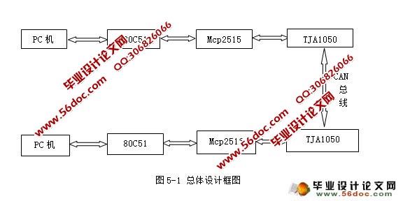
在本次设计中,采用80c51单片机,80c51与PC机通信,PC发送数据到串口,串口调用发送函数经过单片机通过SPI将数据写入mcp2515并通过CAN收发器发送;CAN总线传输过来的数据经过CAN收发器接受并写入mcp2515,调用CAN发送函数经过单片机读取数据上传给PC机。如图5-1为本次设计的总体设计框图。
串口程序负责计算机和单片机之间的数据传输,SPI接口程序负责单片机和CAN通信模块的数据传输。
发送数据子程序负责CAN节点数据的发送,发送数据时,首先要清空发送请求标志位,然后启动MCP2515控制器,将发送缓冲区中的数据发送出去。
接收数据子程序相比发送数据子程序要稍微麻烦一点,接收数据子程序负责CAN节点数据的接收以及其它特殊情况的操作处理。但是在接收数据的过程中,我们要对CAN总线中断、出错、溢出、是否有数据等特殊情况进行处理。
   目 录
摘 要 i
Abstract ii
第一章 绪 论 1
一、 课题背景 1
二、 选题目的 1
三、 选题意义 1
第二章 单片机简介 1
一、 单片机最小系统 1
(一) 晶体振荡器电路 3
(二) 复位电路 4
(三) Max232接口电路 5
第三章 CAN总线介绍 8
一、 CAN总线基本概念 8
二、 CAN总线的发展概况 9
三、 CAN总线协议 11
第四章 硬件设计原理及方案 14
一、 硬件设计原理 14
(一)、 微控制器STC89C52RC简介 14
(二)、 单片机最小系统 15
(三)、 CEPARK MCP2515 16
第五章 硬件设计方案 20
一、硬件总体设计 20
二、用Pico示波器进行can总线解码分析 20
(一) can总线上传输的电平特点 21
(二) 解码设置 21
(三) 从picoscop6中设置解码数据 21
第六章 结果分析 23
一、 STC单片机ISP控制软件进行实际操作演示 23
二、 单片机与can总线的连接。 24
三、 点对点通信的实现 25
四、 实现通讯结果的测试 26
结 论 28
致 谢 29
参考文献 30
外文原文 31
中文翻译 37 |