摘 要
本课题的主要内容就是用单片机实现数字电子钟的设计。利用单片机的特点,通过编写程序来控制产品实现设计需要的功能。
该电子钟使用12MHZ 晶振与单片机AT89C51 相连接,通过软件编程的方法实现以24 小时为一个周期,同时用6位7段LED数码管显示小时,分钟和秒的要求,并在计时过程中具有定时功能,当时间到达提前定好的时间进行蜂鸣报时。时钟控制方面,该电子钟设有四个按键: S1、 S2 、S3和S4 键,进行相应的操作就可实现校时、定时、复位功能。AT89C51是低功耗、高性能的CMOS 型8位单片机。片内带有4KB 的Flash 存储器,且允许在系统内改写或用编程器编程。另外,AT89C51 的指令系统和引脚与8051 完全兼容,片内有128B 的RAM 、32条I/O 口线、2个16 位定时计数器、5个中断源、一个全双工串行口等。
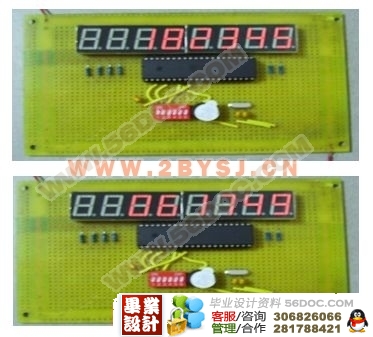
在课题中还有一个任务就是我们的显示模块,由于要显示时、分、秒需要6位数字,为了方便,我们用两个四位一体数码管来显示时间所以如何通过编程来控制数码管的显示也是一个重点。
关键词:单片机; 电子钟; AT89C51; 晶振
ABSTRACT
The main Purpose of this topic is the design that uses Single Chip Microcosm to carry out the numerical electric clock. Make use of Single Chip Microcosm’s the characteristics of the machine, the product that passes to write procedure to control us carries out the function of our demand.
This electron clock is connected to the MCU AT89C51 by the 12MHZ crystal oscillator. With software programming, the clock can display hour, minute and second at the same time in a 24 -hour cycle. It can give correct time with a buzzer when it is on the hour. This kind of electron clock is equipped with three keys, S1, S2 and S3, which enable the clock to adjust to keep accurate time and to buzz at the set time.
The AT89C51 is a low-power, high-performance CMOS 8-bit microcomputer with 4K bytes of Flash Programmable and Erasable Read Only Memory (PEROM).The AT89C51 provides the following standard features: 4K bytes of Flash, 128 bytes of RAM, 32 I/O lines, two 16-bit timer/counters, a five vector two-level interrupt architecture, a full duplex serial port, on-chip oscillator and clock circuitry.
In the topic still have a task is our display module, In order to display the time we need 6 position digits, for the sake of the convenience, we display time with two four position integral whole tube, so how to pass the programming is also a point to the control figures tube display.
Key words: single chip microprocessor; electronic clock ;at89c51 ;crystal;
毕业设计应完成的主要工作:
1.编写实现该功能的程序(系统监控程序;报时定时程序;);
2.功能电路的设计;
3.利用仿真系统进行功能仿真和调试;
4.掌握电路的设计,组装与调试方法。
本文设计了基于单片机的多功能数字钟的总体方案,对装置软、硬件的设计作了详细研究,并进行了相应的软件和硬件调试。该数字钟采用AT89C51单片机作为核心控制芯片,完成整点报时、显示、定时功能。
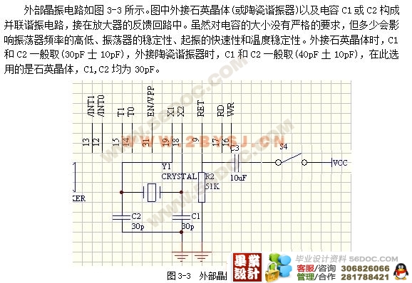
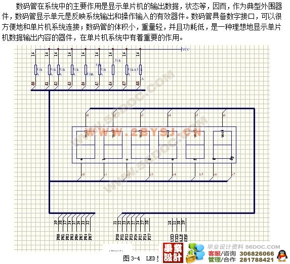
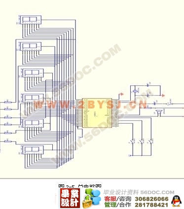
整个系统分为几个小的电路,分别实现各自的功能。晶振电路,12MHZ晶振和两个30pF电容构成并连谐振接到X1和X2口。复位电路,在RST复位输入引脚上接一10uF电容至VCC端,下接一个51K电阻到地。控制电路,4个按键控制,进行调时,定时,复位操作。显示电路,用6位7段数码管进行时,分,秒的显示。
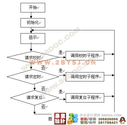
装置中软件设计部分包括一个主程序、四个模块程序和二个子程序,各自执行自己的功能,完成定时,调时等设操作。本文从整体到部分详细介绍了数字钟的设计,在比较重要的部分进行了详细的论述,并且给出了程序框图及说明。
目 录
第一章 单片机的选择 1
第一节 单片机的发展概况及其选择 1
第二节 AT89C51单片机性能与应用 1
一、 性能特点 1
二、 引脚功能 1
三、 振荡器电路设计 3
四、 复位电路的设计 3
五、 存储器的配置 4
六、 7段数码管工作原理 5
第二章 软件设计 7
第一节 主函数设计 7
一、 系统流程图 7
二、 内部计时子程序流程图 8
三、 校时子程序流程图 10
第三章 硬件设计 12
第一节 整体电路结构设计 12
第二节 控制电路设计 12
第三节 晶振电路设计 13
第四节 LED显示电路 14
(毕业设计网 )
第五节 整体电路 15
第四章 软件仿真及硬件调试 16
第一节 仿真器介绍 16
第二节 仿真器编程 17
第三节 调试结果 18
结 论 19
致 谢 20
参考文献 21
附录:源程序代码 22 |
