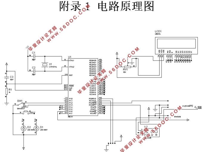
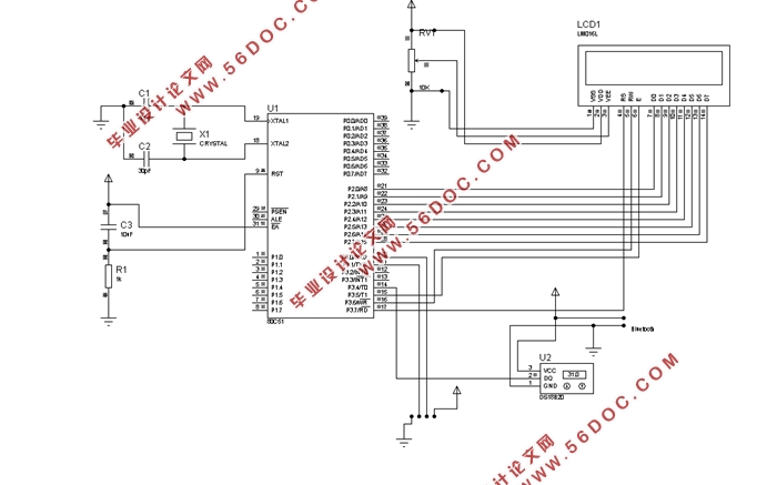
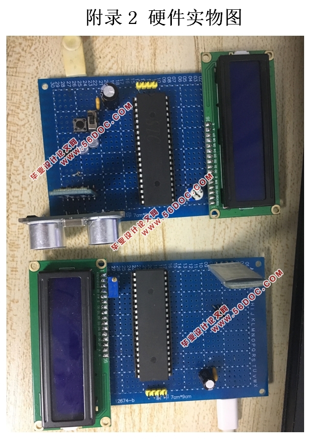
基于单片机的智能车库调度系统设计(附电路原理图,实物图)(任务书,开题报告,外文翻译,论文12000字)
摘要
随着汽车的普及,车库已经成为了人们生活中不可或缺的一部分。生活节奏的加快导致传统的车库并不能满足人们的需求。本文设计了智能车库调度系统,采用单片机作为控制芯片,外围传感器探测外部环境并传送数据给单片机,经过单片机的计算处理后,发送信号到外围驱动电路,实现车库的计数以及开关。本设计由电源模块、温度检测模块、LCD显示模块、超声波测距模块、蓝牙模块、门开关模块以及其它电路构成,其中电源模块负责给智能车库供电,温度传感器用来测量温度,LCD显示模块用来显示车辆数目以及当前状态,超声波模块用于测量距离,蓝牙模块用于实现无线验证,门开关电路用来控制车库门的状态。首先,温度传感器测量温度,然后超声波测距模块检测车辆距离,之后单片机计算车辆距离,其次蓝牙模块实现两个单片机之间数据传输,再之后单片机判断验证状态,最后通过设定好的程序完成车库的计数以及控制门的开关等一系列操作;切换到手动模式后,可以通过手动直接控制门的开关。
关键词:智能车库 超声波测距 单片机 温度传感器 蓝牙
The Intelligent Garage Dispatching System Based on MCU
Abstract
With the popularity of cars, the garage has become an integral part of people's lives. As the pace of life , resulting in the traditional garage can not meet people's needs. This paper designs the intelligent garage dispatching system, using the single chip microcomputer as the control chip, the peripheral sensor detects the external environment and transmits the data to the single chip computer. After the calculation process of the single chip computer, sends the signal to the peripheral driving circuit, realizes the garage count and the switch. The design includes the power module, temperature detection module, LCD display module, ultrasonic distance measurement module, Bluetooth module, door switch module and other circuits. The power module is responsible for the power supply module to the intelligent garage, the temperature sensor is used to measure the temperature, LCD display module is to display the number of vehicles and the current state, the ultrasonic module is used to measure the distance, the Bluetooth module is used for wireless verification and the door switch circuit is used to control the status of the garage door. First, the temperature that is measured by temperature sensor is sent to the MCU, then the distance that is detected by the garage of the ultrasonic distance detection module is sent to the MCU. Then the MCU calculate the vehicle distance. Secondly, the bluetooth module transfers data between the two MCU Single-chip to determine the status of verification. Finally, the garage completes the garage count and control the door switch and a series of operations through the set procedures. You can control the door manually when you switch to manual mode.
Keywords:intelligent garage;ultrasonic distance detection;MCU;temperature sensor;bluetooth


目 录
摘要 I
Abstract II
第一章 绪论 6
1.1 课题研究的背景和意义 6
1.2 课题研究的主要内容 6
1.2.1 智能车库调度系统主要功能 6
1.2.2 本文主要工作 7
第二章 智能车库调度系统的主要功能和方案设计 8
2.1 智能车库的整体方案 8
2.1.1 设计原理 8
2.1.2 系统框图 8
2.3 不同模块的方案设计 10
2.3.1 单片机方案的设计 10
2.3.2 测距模块方案设计 10
2.3.3 电源模块方案设计 10
2.3.4 测温模块方案设计 10
2.3.5 显示模块方案设计 10
2.3.6 门开关模块方案设计 11
2.3.7 验证模块方案设计 11
2.4 本章小结 11
第三章 智能车库调度系统的硬件电路设计 12
3.1 单片机最小系统电路 12
3.1.1 晶振电路 12
3.1.2 复位电路 13
3.2 LCD显示电路 13
3.3 超声波测距模块电路 14
3.4 蓝牙模块电路 14
3.5 LED选择控制电路(表示门开关状态) 15
3.6 温度传感器电路 15
3.7 电源模块接口电路 16
3.8 本章小结 16
第四章 智能车库调度系统的软件设计 17
4.1 主机软件设计思路 17
4.1.1 软件构成 17
4.1.2 整体流程 18
4.2 主机初始化程序设计 18
4.3 主机自动模式程序设计 19
4.3.1 测温程序 21
4.3.2 LCD显示程序 22
4.3.3 蓝牙认证程序 22
4.4 主机手动模式程序设计 23
4.5 从机软件设计思路 23
4.5.1 软件构成 23
4.5.2 整体流程 24
4.5.3从机蓝牙程序设计 25
4.6 本章小结 25
第五章 仿真与调试 26
5.1 软件仿真 26
5.1.1 自动模式的仿真 26
5.1.2 手动模式仿真 28
5.1.3 蓝牙串口通信的仿真 28
5.2 硬件调试 30
5.2.1 自动模式的调试 30
5.3 结果简述 32
5.4 问题反思 32
5.5 本章小结 33
结 语 34
参考文献 35
致 谢 37
附录1 电路原理图 38
附录2 硬件实物图 39
|


