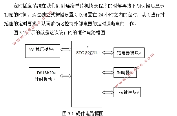
基于单片机的定时插座设计(开题报告,论文13000字)
摘要
我们人类的跨越时代的智能化的电子时代其实是由单片机开创的,大多数我们人类看起来比较复杂的系统如果能够交给单片机进行设计,往往能够收获到我们意想不到的使得电路层次更加简单、功能更加齐全的完美的效果。
目前随着时代的进步,人们的生活水平以不可思议的速度提升了,因而人们对家用电器的需求越来越高,从而导致家用电器越加地普及了,为了节能以及方便和其他方面的一些因素,家用电器的定时功能的需求同时也加一步地被人们看重了。而定时开关插座被利用在空调、台灯、热水器等多种在供电的时候需要被定时的电器上面。使用的时候,插座应该需要做安全,方便,节能等。本篇文章介绍了这样一种基于STC89C51单片机的定时插座设计。
本文首先叙述了定时插座设计需要实现的功能,主要由KEIL软件实现,用uvproj文件编写程序,用LCD12232作为显示屏,用DS18b20作为定时器。本设计主要有选择设计方案、介绍相关元器件及设计多种外围电路,接下来还有软硬件电路的调试。最后还有程序编写及实物展示。
关键词:STC89C51;定时插座; 单片机;uvproj;LCD12232;DS18b20
Timing Socket Design Based On MCU
Abstract
Our humanity's spanning time intellectualization Electronic Age are actually found by the monolithic integrated circuit, the majority our humanity looks like the quite complex system if can give the monolithic integrated circuit to carry on the design, often can receive us unexpectedly to cause the electric circuit level to be simpler, a function more complete perfect effect.
At present along with time development, people's rhythm of life sped up by the inconceivable speed, thus the people are more and more high to the domestic electric appliances demand, thus caused the domestic electric appliances all the more to popularize, in order to conserve energy as well as the convenience and other aspect some factors, the domestic electric appliances fixed time the function demand simultaneously also added step place to regard as important by the people. But time cut-out plug use in air conditioning, desk lamp water heater and so on many kinds of in power supply time needs by the fixed time electric appliance above. The use fixed time plug should need to achieve safe, convenient as well as the energy conservation and so on. This article approached everybody to introduce such one kind of design proposal: Based on STC89C51 monolithic integrated circuit fixed time plug.
This article first introduced the function of timing socket design need to implement, Mainly by the KEIL software implementation, using uvproj file, display with LCD12232, timer with DS18b20. This design mainly has the choice design proposal, the introduction correlation primary device and the design many kinds of periphery electric circuit, meets down also has the programming and the material object demonstration. Finally also has the software and hardware electric circuit debugging.
Key words: STC89C51; Timing socket; MCU; uvproj;LCD12232;DS18b20
2.1.1 方案的设计
时间插座系统是不做任何操作,按确认显示初始时间。当我们按下设置键的时候定时插座就会让我们进入到设置界面中去,每当我们按一次设置键就会进入到下一个设置界面中去,然后我们就可以进行相应的设置操作了。具体点说,我们可以依次进行时间、定时的设置。总体而言可以实现24h之内的定时开关机,或者一定时间段内的开关,从而起到控制电器工作的基本目的。
2.1.2、结构与功能
设计方案的大体设计主要可以实现出以下的4个方面:
(1)人机交互界面:通过借助12232液晶显示屏,和独立按键建立起一套比较完善的人机交互界面。这个可以进行人机交互的界面可以用来相关设置定时的参数。用户可以直接观察定时的参数以及定时的时间。
(2)设置定时时间:用户可以使用人机界面找到时间设置界面,可设置时间,让用户可以设置相应的每个组设定时间。
(3)设置现实时间:因为各种外界因素可能会导致系统的现实时间与实际的现实时间存在一定的差异,因此系统是支持修改系统现实时间的[6]。用户可以通过人机交互界面,从而找到设置界面的时间设置的实时系统,以避免时间可能会有区别差异。
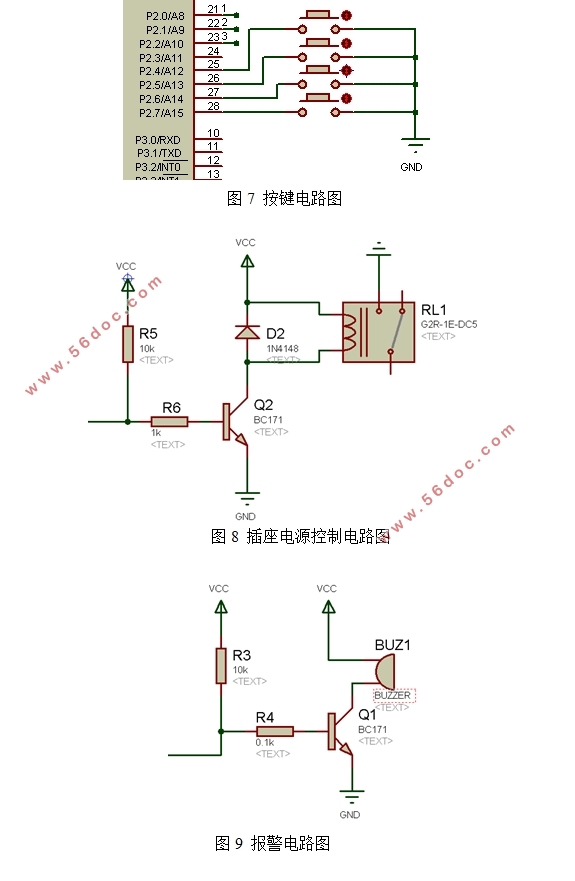
(4)报警:当用户设定的时间结束的时候会出现报警提示用户的声音,因此可以提醒用户了。
目录
摘要 I
Abstract II
第一章 绪论 III
1.1 定时插座的研究背景 1
1.2 目前在国内外的发展以及未来的前景 2
1.3 需要克服的困难 4
第二章 设计方案 5
2.1 设计任务 5
2.1.1 方案的设计 5
2.1.2 结构与功能 5
2.2 设计方案的选择 5
2.2.1 方案的选择 5
2.2.2 单片机芯片的选择 6
2.2.3 显示模块的选择 6
2.2.4 时钟模块的选择 6
2.2.5 控制插座设备的选择 7
2.2.6 按键的选择 7
2.2.7 电源方案的选择 8
2.2.8 显示方式的选择 8
第三章 外围电路主要元件介绍 9
3.1 单片机STC89C51简介 9
3.1.1 主要特性 9
3.1.2 引脚功能说明 10
3.1.3 主要模式 10
3.2 LCD12232系列点阵型液晶显示模块 10
3.2.1 工作参数 11
3.2.2 液晶驱动IC基本特性 11
3.2.3 模块基本特性 11
3.2.4 外形尺寸图 11
3.2.5 电气特性 12
3.2.6 接口时序 12
3.3 DS18b20的介绍 14
3.3.1 DS18b20方框图如下 14
3.3. DS18b20的引脚排列如下 14
3.3.3 DS18b20的硬件结构如下 15
第四章 外围电路 16
4.1 电源电路 16
4.2 单片机最小系统电路 16
4.3 时钟电路 17
4.4 复位电路 18
4.5 LCD12232显示电路 18
4.6 继电器驱动电路 19
4.7 按键电路 19
4.8 插座电源控制电路 19
4.9 报警电路 20
第五章 软硬件设计 20
5.1 主程序流程图及程序 21
5.2 定时程序(TIMETICK.c) 26
第六章 系软硬件调试 28
6.1 硬件制作 28
6.2 硬件电路部分的调试 28
6.2.1 独立元件的检测 28
6.2.2 电源电路的调试 29
6.2.3 单片机STC89C51最小系统的软硬件调试 29
6.2.4 显示模块的调试 30
6.2.5 键盘模块的调试 30
6.2.6 继电器电路的调试 30
6.3 软件调试 30
6.3.1 显示模块调试 30
6.3.2 时钟模块调试 30
6.3.3 键盘模块调试 30
6.3.4 人机界面模块调试 30
6.3.5 大体硬件图 30
6.3.6 实物调试图 31
结束语 34
参考文献 35
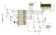
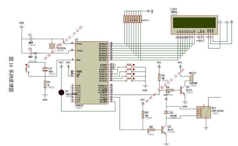
附录一 系统原理图 37
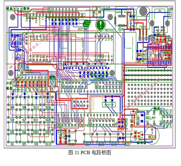
附录二 PCB电路板图 38
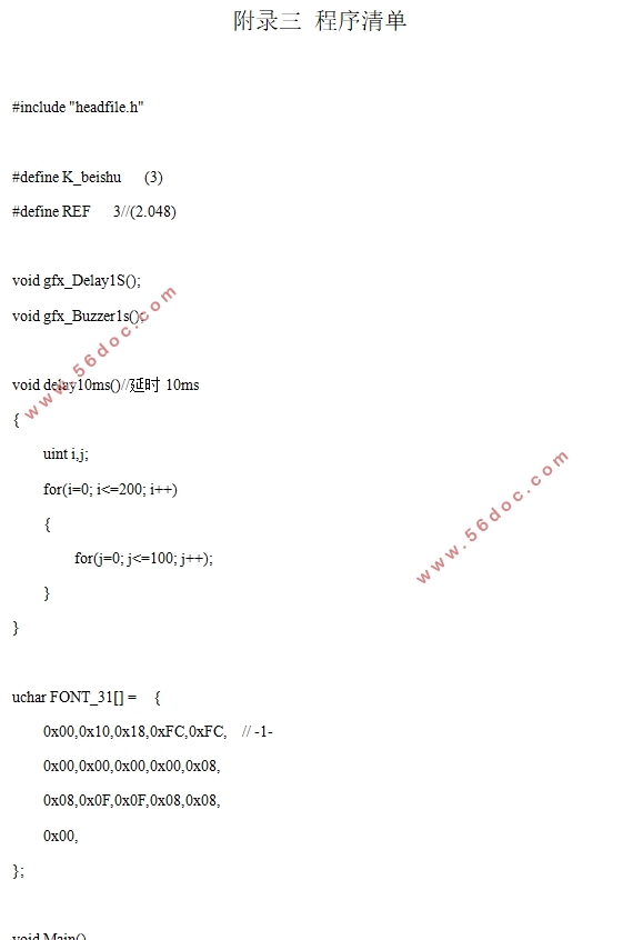
附录三 程序清单 39
|