基于AT89C52单片机的通信协议设计
来源:56doc.com 资料编号:5D25687 资料等级:★★★★★ %E8%B5%84%E6%96%99%E7%BC%96%E5%8F%B7%EF%BC%9A5D25687
资料以网页介绍的为准,下载后不会有水印.资料仅供学习参考之用. 密 保 惠 帮助
资料介绍
基于AT89C52单片机的通信协议设计(论文10000字)
摘要
无线组网由于其便利性,正受到越来越多的重视。由于各种高性能的无线通信协议相继诞生,无线设备的性能也跟着逐渐增强。事实上,随着小型无线射频芯片的诞生,不具备无线射频电路方面知识的人也可以开发自己的无线通信模块,这使得本次的通信设计成为可能。
本次设计将实现基于CC2500无线射频芯片的多机通信,所使用的网络模型为国际标准化组织的OSI参考模型的物理层、数据链路层和网络层这三层。在硬件上,本次设计将使用STM32控制CC2500的通信流程;在软件上将采取分层设计,明确整体的通信流程以及物理层、数据链路层、网络层的功能及流程;在调试部分中,计算机将被用来设置通信设备的网络参数,协议的实现效果也将在计算机上显示。最后总结本次设计的不足。
关键词:无线通信协议OSISTM32CC2500
A Wireless Communication Protocol Based on CC2500
Abstract
Wireless networking has been paid much attention due to its convenience.Also,the performance of wireless devices is gradually increased, attributing the success to the excellent wireless protocols. The knowledge of radio-frequency communication circuits is no longer a barrier to anyone who wants to develop a wireless communication module, which makes this project possible.
This project will realizethe communication among multiple stations based on the CC2500 RF chip, by using the physical layer, data link layer and network layer of OSI module. In circuit design part, the STM32 MCU is used to control the whole communication procedure of CC2500; the software design will use the layered design method. Total communication process will be introduced first. Then the function and process of the physical layer, data link layer and network layer will be on the table.The computer will be used to set up the network parameters of the communication station and display the procedure of the communication process. At last, the disadvantages of this project will be discussed.
Key words: wireless communication protocol, OSI module, STM32, RF chip CC2500


目录
摘要 I
Abstract II
目录 3
第一章引言 5
1.1 相关背景 5
1.1.1 无线通信的射频电路 5
1.1.2 无线通信协议 5
1.2应用方向 6
1.3 设计内容及方式简介 6
1.4 本次设计的目的及意义 7
1.5 本文结构 7
第二章硬件电路设计 1
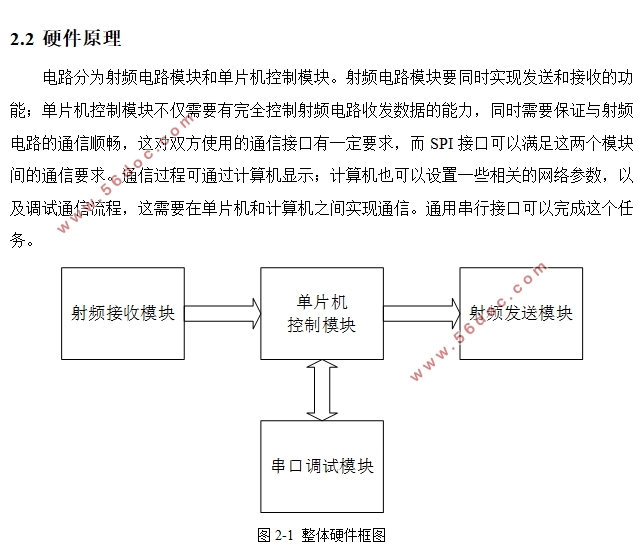
2.1 硬件功能分析 1
2.2 电路模块分析 1
2.2.1 MCU模块电路 1
2.2.2 射频电路模块 4
第三章协议软件实现 6
3.1 OSI设计参考模型简介 6
3.2 开发环境介绍 6
3.2.1 STM32固件库 6
3.2.2 keil MDK开发环境 6
3.3 协议分层设计及实现 7
3.3.1 物理层 7
3.3.2 数据链路层 8
3.3.3 网络层 10
3.3.4 主函数流程 15
第四章调试结果分析 18
4.1 调试方案介绍 18
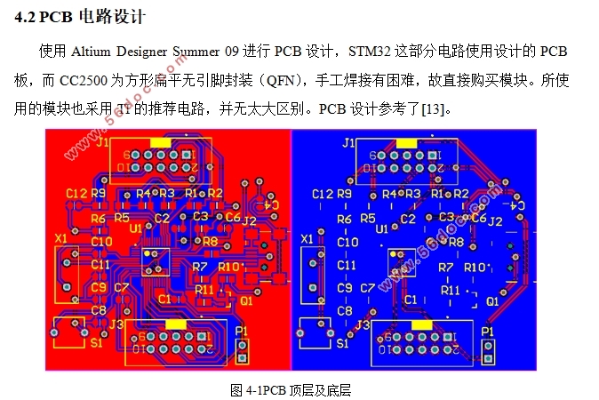
4.2 PCB电路设计 18
4.3 总结 20
结语 21
参考文献 22
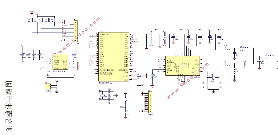
附录整体电路图 23
|


