基于51单片机脉搏测量仪的设计
来源:56doc.com 资料编号:5D27040 资料等级:★★★★★ %E8%B5%84%E6%96%99%E7%BC%96%E5%8F%B7%EF%BC%9A5D27040
资料以网页介绍的为准,下载后不会有水印.资料仅供学习参考之用. 密 保 惠 帮助
资料介绍
基于51单片机脉搏测量仪的设计(论文12000字)
摘 要
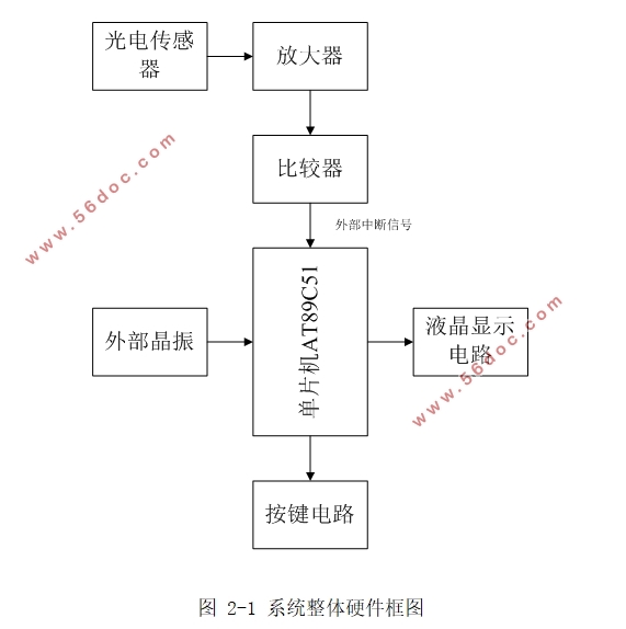
本次设计的脉搏测量仪是基于51单片机来实现的。通过检测脉搏信息,使我们能够及时了解到自己的身体状况。系统由AT89C51单片机控制,通过光电传感器检测得到脉冲信号,这个信号经过滤波器后再进行整形放大处理,最后由单片机对这个信号进行计数,这样就能得到我们需要的脉搏值了。系统还设定了脉搏上下限报警值以及一个检测脉搏时的指示灯,通过观测指示灯的闪烁,我们能更精确的测出脉搏值。系统停止运行时,能够显示总的脉搏次数和时间,但是由于系统稳定性点不足,测出的脉搏值有细微的误差。经过最后测试,系统能正常工作,达到本次设计要求。
关键词:脉搏测量仪;滤波器;光电传感器
Pulse measuring instrument
Abstract
The design of the pulse measuring instrument is based on 51 micro controller to achieve.By detecting the pulse information to enable us to be kept informed of their physical condition.AT89C51 micro controller system control, obtained by photoelectric sensors to detect a pulse signal, the signal passes through a filter and then shaping the enlargement process, and finally by the micro controller signals are counted so that we can get the value we need a pulse.The system also set a lower limit on the value of the pulse and alarm indicator when a pulse is detected by observing the flashing lights, we can more accurately measure the pulse value.When the system stops functioning, it is possible to display the total pulse frequency and duration, but due to lack of stability of the system point, the measured pulse values are subtle errors.After the final test, the system can work to achieve this design.
Keywords: photo sensor;filter;;photoelectric sensors

目 录
摘 要 I
Abstract II
第一章 绪论 1
1.1 选题的背景和意义 1
1.2 脉搏测量仪的发展与应用 2
1.3 本课题需要完成的任务 2
1.4 本文的主要结构 3
第二章 总体方案的论证与设计 4
2.1传感器模块的选择 4
2.2信号处理模块的选择 4
2.3主控模块的选择 5
2.4显示模块的选择 5
2.5电源模块的选择 6
2.6系统整体设计概述 6
2.7 系统整体硬件框图 6
第三章 系统硬件电路设计 8
3.1主控模块 8
3.1.1主控模块的简单说明 8
3.1.2 AT89C51单片机的中断系统 8
3.1.3单片机最小系统设计 8
3.2 LCD1602液晶显示器简介 9
3.2.1 液晶原理介绍 10
3.2.2液晶显示部分与AT89C51的接口 10
3.3信号采集电路设计 11
3.3.1传感器简介 11
3.3.2滤波电路 12
3.3.3放大整形电路 13
3.4电源模块电路 14
3.5按键部分电路 14
第四章 系统软件设计 15
4.1系统软件总体设计 16
4.1.1 系统总流程图 16
4.1.2 按键子模块流程图 17
4.1.3 液晶显示部分流程图 17
4.2程序设计原理 18
4.3 程序分析 19
4.3.1 LCD1602初始化设置 19
4.3.2 独立按键程序 20
4.3.3设置函数 21
4.3.4 报警函数 21
第五章 系统调试 22
5.1软件调试 23
5.2硬件调试 23
5.3调试结果 24
5.4误差分析 24
第六章 总结与展望 25
参考文献 26
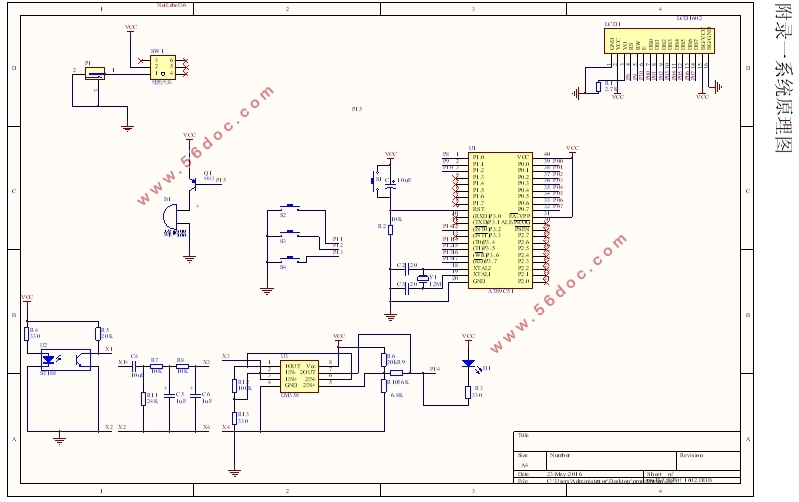
附录一系统原理图 28
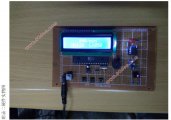
附录二硬件实物图 29
致谢 30 |