基于52单片机的智能家居设计
来源:56doc.com 资料编号:5D27918 资料等级:★★★★★ %E8%B5%84%E6%96%99%E7%BC%96%E5%8F%B7%EF%BC%9A5D27918
资料以网页介绍的为准,下载后不会有水印.资料仅供学习参考之用. 密 保 惠 帮助
资料介绍
基于52单片机的智能家居设计(任务书,开题报告,外文翻译,论文13000字)
摘 要
科技发展迅速,人就会越加向往轻松舒适且安全的生活。这时,由各种智能化家电构成的智能家居生活就很符合人们的诉求。
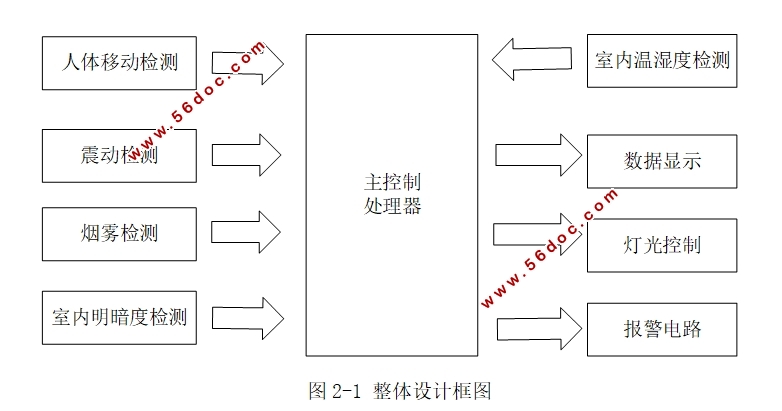
本文先介绍科技的发展由此引出智能家居的概念,然后就其发展现状进行一定说明,并简单点出它的研究意义。接着从总体上对实现本系统的硬件方案进行描述,并针对其中所要用到的部分元器件进行方案的选择。然后,用Altium软件对硬件电路进行设计,用keil软件使用C语言进行编码。
经过了测试后,本次设计功能运行的结果基本符合要求。如安全预警、环境监测和自动控制功能的正常使用,使得此次智能家方案居显得安全又舒适。
关键词:52单片机 智能家居 传感器
Smart Home Design Based on 52 Single Chip Microcomputer
Abstract
Technology is developing rapidly.People will be more aspire to easy and comfortable and safe life. At this time, a smart home lifestyle which is made up of a variety of smart home appliances is in line with people's demands.
At first,this article introduces the development of science and technology. Then it introduces the concept of smart home.Besides the article describes the development status of smart home, and simply point out its research significance.Then the hardware scheme of the system is described in general, and the scheme is selected for some of the components. Then, the hardware circuit is designed with the Altium software. keil software is used to encode with C language.
After the test, the design of the operation meets the requirements basically. For example,safety warning, environmental monitoring and automatic control function of the normal make the smart home program safe and comfortable.
Key words: 52 single-chip; smart home; sensor


目 录
摘 要 I
Abstract II
第一章 绪论 1
1.1 选题背景 1
1.2 发展与现状 1
1.3 本论文主要任务 2
1.4 论文结构安排 2
第二章 智能家居的系统设计 4
2.1 系统总体方案的设计 4
2.2 系统器件的选择 5
2.2.1 主控制芯片的选择 5
2.2.2 显示单元元件的选择 6
2.2.3 供电方式的选择 6
第三章 智能家居系统的硬件设计 7
3.1单片机工作电路 7
3.1.1 STC89C52的简介 7
3.1.2 STC89C52的最小系统电路设计 8
3.3 红外感应电路 10
3.3.1 红外传感器的介绍 10
3.3.2具体电路实现 10
3.4 震动感应电路 10
3.4.1 震动传感器的介绍 10
3.4.2 具体电路实现 11
3.5 烟雾检测模块 11
3.5.1烟雾传感器的介绍 11
3.5.2具体电路实现 12
3.6 温湿度采集电路 12
3.6.1 温湿度传感器的介绍 12
3.6.2 具体电路实现 14
3.7 光强感应电路 14
3.7.1 光照传感器的介绍 14
3.7.2 具体电路实现 14
3.8 按键电路 15
3.8.1按键电路介绍 15
3.8.2 具体电路实现 15
3.9 报警电路 16
3.9.1 蜂鸣器的介绍 16
3.9.2 具体电路实现 16
3.10 显示电路 16
3.10.1 LCD1602的介绍 16
3.10.3 LCD1602的原理图 17
第四章 系统的软件设计 18
4.1 软件开发环境 18
4.2 总程序流程图 18
4.3 LCD显示程序设计 20
4.4 温湿度传感器sht11软件设计 21
4.4.1 温湿度传感器程序的采集流程 21
4.4.2 二线串口通信 21
4.5 防盗报警软件设计 22
4.6 烟雾报警软件设计 23
4.7 自动控制程序设计 24
4.7.1 自动控制程序基本流程 24
4.7.2 IIC串口通信 25
第五章 系统调试 27
5.1 软硬件电路的基本调试方法 27
5.2 系统的软件调试 27
5.3 系统各模块的硬件调试 28
5.3.1 防盗报警模块 28
5.3.2 消防安全报警模块 29
5.3.3 环境检测模块 29
5.3.4自动控制模块 30
第六章 总结与展望 32
6.1 总结 32
6.2 展望 32
参考文献 33
致谢 35
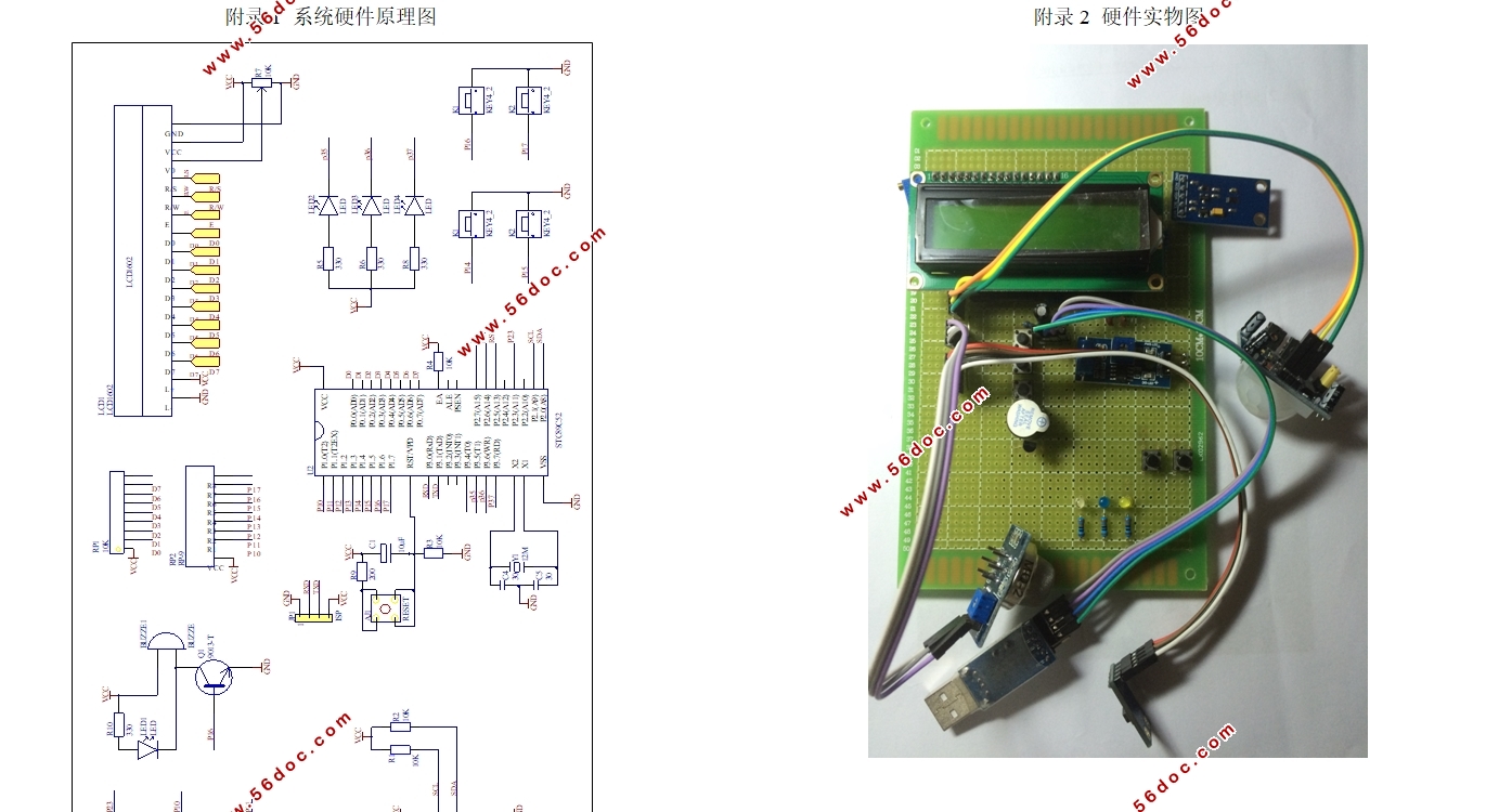
附录1 系统硬件原理图 36
附录2 硬件实物图 37
|


