基于AT89C51单片机抢答器的设计(任务书,开题报告,外文翻译,论文10000字)
摘 要
本设计主要运用了AT89C51单片机定时/计数器的定时及计数原理,用AT89C51单片机和其外围接口实现了抢答器的设计,整个系统可以执行倒计时的功能,使用7段数码管准确地显示倒计时时间以及选手编号。以开关为输入,以扬声器发声和LED显示为输出。其中共设计有简易与扩展两个版本。简易版本中,抢答人数为5人,抢答时间固定为9秒,有人抢答或者倒计时结束会有红灯提示,会有绿灯提示抢答成功者是几号,LED也会显示其编号;在扩展版本中,抢答人数为8人,在开始抢答前抢答为无效,抢答时间可在1到99秒之间设定,抢答成功之后会提供10秒的回答时间,能够显示出哪位选手抢答成功或者抢答犯规,各功能当中均有声音提示。
关键词:单片机 抢答器 Proteus Keil 仿真
The Design of Responder
Abstract
The design of the main use of the AT89C51 microcontroller timer / counter timer and counter principle, using AT89C51 microcontroller and its peripheral interface designed to achieve a Responder, the entire system can perform the function of the countdown, using 7-segment LED display countdown time and accurately contestant number.To switch the input to the speaker output sound and the LED display. Which were designed with simple and extended versions. Easy version, answer number is 5, answer time is fixed at nine seconds, someone will answer or end countdown red tips, green tips Responder winner will be a few numbers, LED will display its number; in the extended version, the answer is number eight, before starting to answer in answer to be invalid, answer time can be set between 1-99 seconds, then 10 seconds to answer in a successful response will be provided time to be able to show which players answer success or answer a foul, the function of which has voice prompts.
Keywords: MCU; responder; Proteus; Keil; simulation
目 录
摘 要 I
Abstract II
第一章 绪论 1
1.1 背景和研究现状 1
1.2 课题内容及研究意义 1
1.3 关于单片机 2
1.4 相关软件 2
1.4.1 Proteus软件 2
1.4.2 Keil软件 2
第二章 系统功能及设计方案 3
2.1 系统功能 3
2.1.1 简易版本基本功能 3
2.1.2 扩展版本扩展功能 3
2.2 系统设计方案 3
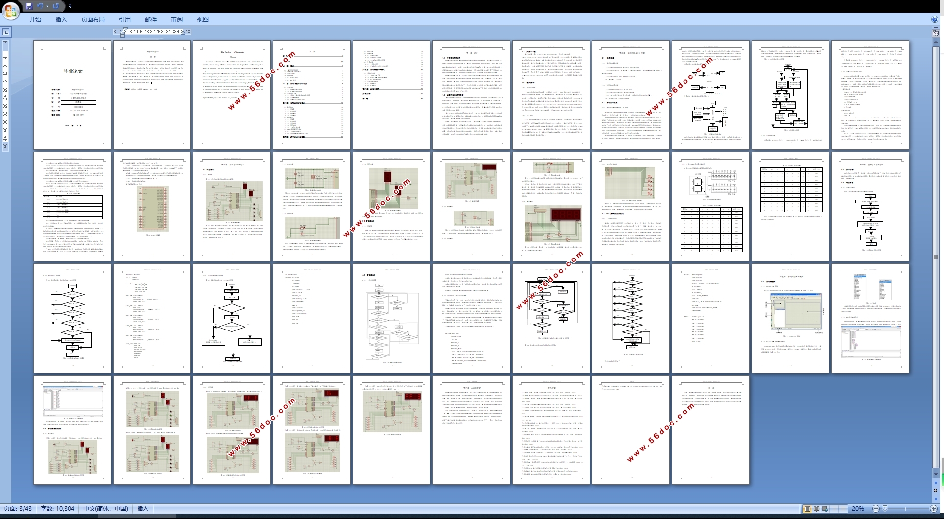
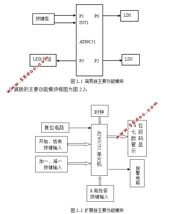
2.2.1 系统的主要功能模块和工作流程 3
2.2.2 系统器材选择 6
2.2.3 主要芯片AT89C51简介 7
第三章 系统总体方案设计 10
3.1 简易版本 10
3.1.1 原理图 10
3.1.2 时钟电路 11
3.1.3 复位电路 11
3.1.4 显示电路 12
3.2 扩展版本 12
3.2.1 原理图 12
3.2.2 时钟电路 13
3.2.3 复位电路 13
3.2.4 显示电路 14
3.2.5 主持人控制电路 15
3.3 LED数码管显示模块 15
3.3.1 LED数码管简介 15
3.3.2 7段位数码管原理图及其段码 16
第四章 程序设计与流程图 20
4.1 设计思想 20
4.2 简易版本 21
4.2.1 主程序流程图 21
4.2.2 外部中断1流程图 21
4.2.3 T0中断处理程序流程图 23
4.3 扩展版本 26
4.3.1 主程序流程图 26
4.3.2 外部中断0(抢答时间的调节) 27
第五章 系统的仿真和测试 31
5.1 系统的仿真 31
5.1.1 Proteus ISIS环境 31
5.1.2 Proteus ISIS绘制电路原理图 31
5.1.3 Keil软件编译程序 32
5.2 系统的测试结果 33
5.2.1 简易版本 33
5.2.2 扩展版本 35
第六章 总结与展望 38
参考文献 39
致 谢 41
|