用单片机实现多功能频率发生器
来源:56doc.com 资料编号:5D3770 资料等级:★★★★★ %E8%B5%84%E6%96%99%E7%BC%96%E5%8F%B7%EF%BC%9A5D3770
资料以网页介绍的为准,下载后不会有水印.资料仅供学习参考之用. 密 保 惠 帮助
资料介绍
摘要
本设计在对直接数字频率合成的原理及其输出信号的性能进行分析的基础
上,采用直接数字频率合成(DDS)的设计方法,对任意波形发生器进行电路设计,利用单片机实现对输出频率和相位的预置及显示的软件控制,通过通信接口下载任意波形数据实现波形数据更新,可产生高分辨率任意波形。
本文对硬件电路设计进行研究,完成了电源模块、单片机系统、DDS芯片等硬件电路设计。
论文最后给出了系统的测量结果,并对误差进行了一定分析。
关键词: 波形发生器、单片机、DDS芯片
Design of multi-frequency Signal--generator Controlled by Single-chip Micro-computer
ABSTRACT
This design in carries on the analysis to the direct digital frequency synthesis's principle and output signal's performance on foundation , uses the direct digital frequency to synthesize (DDS) the design method, carries on the circuit design to the random profile generator, realizes using the monolithic integrated circuit to outputs the frequency and the phase initialization and the demonstration software control, realizes the profile data updating through the correspondence connection downloading random profile data, may produce high resolution random profile The design software and hardware combination of the advantages of full use of the software, play to their strengths as much as possible to reduce hardware overhead. Quickly and easily generate a specific frequency and amplitude of the waveform data; in single-chip control, the use of the circuit generated address, read data, DDS, to obtain the required waveform signals. While the output waveform data stored in data memory, so you can ensure that the waveform data is not lost after power-down.
This paper studies the hardware circuit design, the completion of the power module, SCM system, DDS chips and other hardware design.
Finally the measurement results of the system is given, and some analysis of error.
Keywords: Waveform Generator、Single-chip、DDS chip、
目录 21000字
摘要 III
ABSTRACT IV
第1章 绪论 - 1 -
1.1研制任意波形发生器的意义 - 1 -
1.2国内外动态 - 2 -
1.3 任意波形发生器实现方式 - 3 -
1.3.1程序控制输出方式 - 3 -
1.3.2 DMA输出方式 - 3 -
1.3.3可变时钟计数器寻址方式 - 3 -
1.3.4 直接数字频率合成方式 - 4 -
1.4 本设计所做主要工作 - 4 -
第2章 系统整体设计 - 6 -
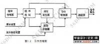
2.1系统原理 - 6 -
2.2系统任务 - 7 -
2.2.1频率合成技术概述 - 7 -
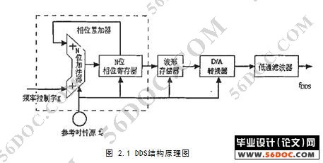
2.2 DDS的基本原理及性能特点 - 8 -
2.3专用DDS芯片电路分析 - 10 -
2.3.1 AD9850的结构及功能 - 11 -
2.4 AD8950芯片的控制电路和控制时序 - 12 -
2.5 单片机简介 - 14 -
第三章 系统硬件设计 - 16 -
3.1信号的产生与控制电路设计 - 16 -
3.1.1 DDS电路 - 16 -
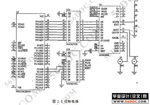
3.1.2 MCU控制电路 - 18 -
3.2人机交互电路设计 - 19 -
3.2.1键盘输入电路 - 19 -
3.2.2 液晶显示电路 - 20 -
3.2.3通信接口电路 - 21 -
3.3信号处理电路设计 - 22 -
3.3.1低通滤波器的设计 - 22 -
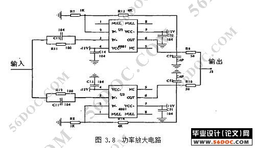
3.3.2 输出放大电路 - 24 -
3.4电路设计中注意的问题 - 25 -
3.4.1电源与接地的处理 - 25 -
3.4.2 数模混合电路与空余管脚的处理 - 26 -
3.4.3 PCB中的其它抗干扰措施 - 26 -
3.5系统的杂散噪声处理 - 26 -
第4章 系统软件设计 - 29 -
4.1系统编程语言和编程工具 - 29 -
4.2软件总体设计 - 29 -
4.3 主监控程序模块 - 30 -
4.4信号产生软件的设计 - 32 -
4.5串行通信程序设计 - 33 -
第5章 系统测试 - 36 -
5.1系统使用环境 - 36 -
5.2系统使用说明 - 36 -
5.3系统性能指标 - 38 -
第6章 总结与展望 - 39 -
6.1 总结 - 39 -
6.2展望 - 39 -
参考文献 - 40 -
致谢 - 41 -
|