某轻型越野车循环球转向器设计(含CAD图,CATIA三维图)
来源:56doc.com 资料编号:5D22480 资料等级:★★★★★ %E8%B5%84%E6%96%99%E7%BC%96%E5%8F%B7%EF%BC%9A5D22480
资料以网页介绍的为准,下载后不会有水印.资料仅供学习参考之用. 密 保 惠 帮助
资料介绍
某轻型越野车循环球转向器设计(含CAD图,CATIA三维图)(,论文说明书11500字,CAD图5张,CATIA三维图)
摘要
汽车作为一种商品在世界各地都拥有广阔的前景,又因为它的大批量生产和销售从而给企业带来丰厚可观的利润。汽车一个最基础的要求就是保持直线行驶和进行转弯,这两种基本要求都需要转向系的参与,由此可见转向系统是汽车所有系统中一个重要的机构。从最近的几年来看,不难看出循环球转向器因为它自身的各种优点在汽车转向系统上得到广泛使用。根据国家标准和某轻型越野车相关参数,参考了汽车设计和相关书籍资料,本文主要设计了循环球转向器中的螺杆、螺母和齿扇等相关重要零件并进行了相应的强度校核分析。最后根据所设计出的循环球转向器参数利用CATIA画出部分重要零件的三维图,并生成二维图。
关键词:循环球 转向器 设计 校核 建模
Abstract
Automobile, as a commodity, has broad development prospects all over the world, the mass production and large-scale sales of which bring considerable profits to auto companies. Being an important part in all automotive systems, the steering system is required for vehicles to maintain or change the direction of travel. In recent years, the recirculating ball steering gear has been widely used due to its various advantages. According to national standards and relevant parameters of a light off-road vehicle, and referring to related books and information on vehicle design, this paper is to design some indispensable parts of the recirculating ball steering gear such as screws, nuts and fan-typed shafts, with corresponding strength check and analysis performed. Finally, based on the parameters of the designed recirculating ball steering gear, this paper utilizes CATIA to draw three-dimensional diagrams that generate corresponding two-dimensional diagrams.
Key Words: recirculating ball; steering gear; design; check; modeling.
目录
第一章 绪论 1
1.1课题背景 1
1.2国内外研究现状 1
1.3研究目的和意义 1
1.4研究对象及主要内容 2
1.5经济性分析 2
第二章 机械转向系简介 3
2.1转向操纵机构 3
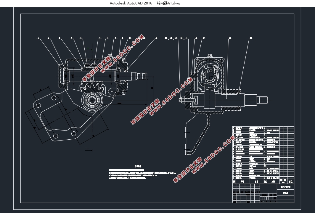
2.2转向器简介 4
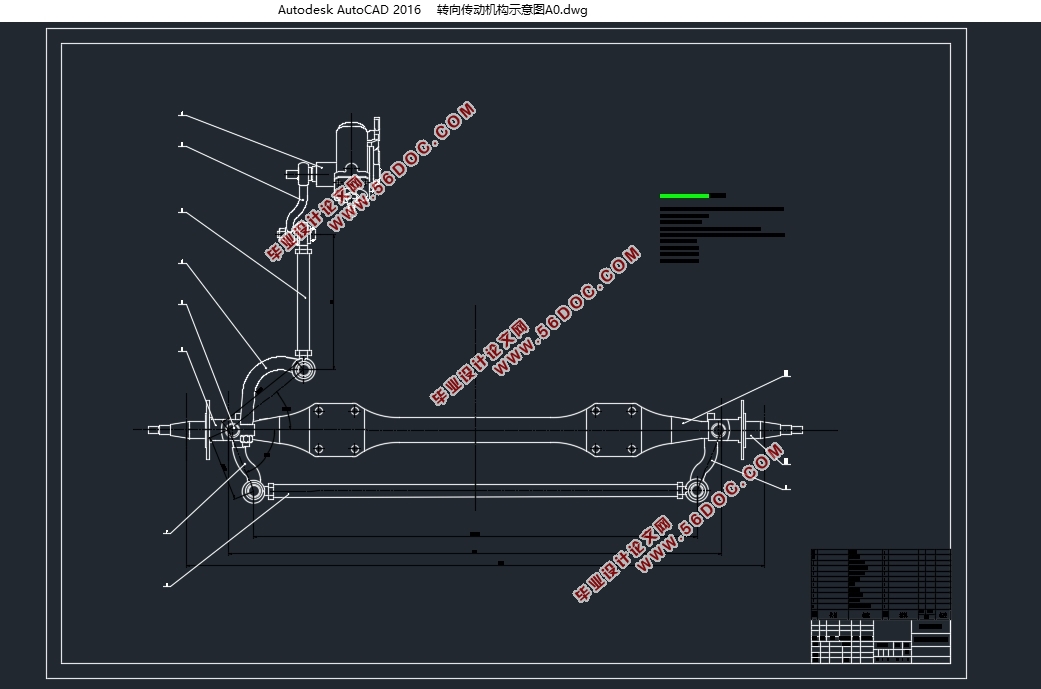
2.3转向传动机构 5
第三章 转向系结构设计 6
3.1转向器的效率 6
3.1.1转向器的正效率 6
3.1.2转向器的逆效率 7
3.2传动比的变化特性 7
3.2.1转向系传动比 7
3.2.2力传动比与转向系角传动比的关系 8
3.2.3转向系的角传动比 9
3.2.4转向器角传动比及其变化规律 9
3.3转向器传动副的传动间隙 9
3.3.1转向器传动副的传动间隙特性 9
3.3.2如何获得传动间隙特性 10
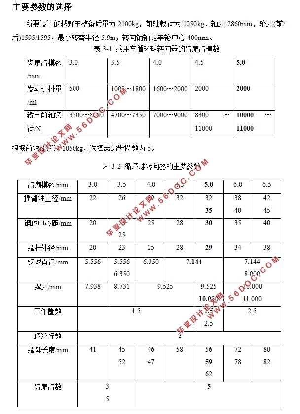
3.4主要参数的选择 11
3.5螺杆、钢球、螺母传动副设计 13
3.5.1钢球中心距 、螺杆外径 螺母内径尺寸 13
3.5.2钢球直径d及数量n 14
3.5.3滚道截面 14
3.5.4接触角 15
3.5.5螺距 和螺旋线导程角 15
3.5.6工作钢球圈数W 15
3.5.7导管内径d1 15
3.5.8方向盘的总转动圈数 16
3.6齿条、齿扇传动副设计 16
第四章 主要零部件校核 18
4.1转向盘受力确定 18
4.2钢球与滚道间的接触应力 19
4.3齿的弯曲应力 20
4.4转向摇臂轴直径的确定 21
第五章 三维建模 22
5.1转向螺杆的建模 22
5.2转向摇臂轴的建模 24
5.3转向器壳体的建模 26
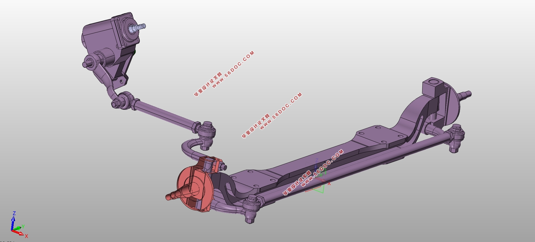
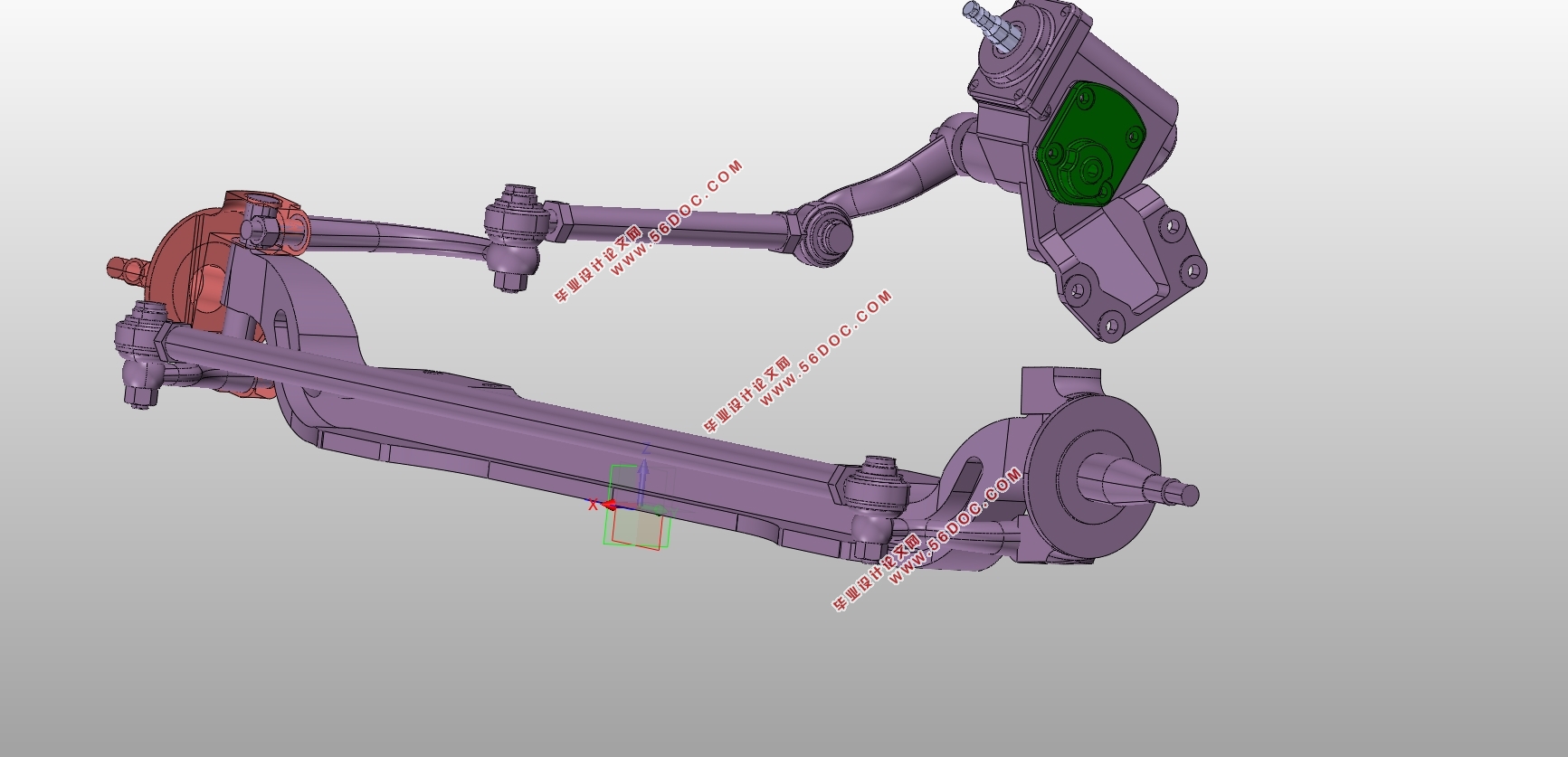
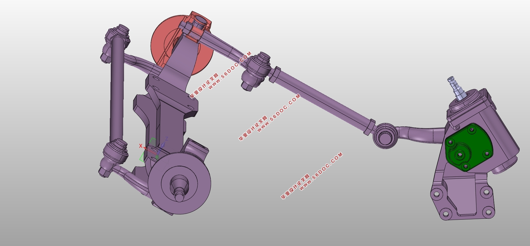
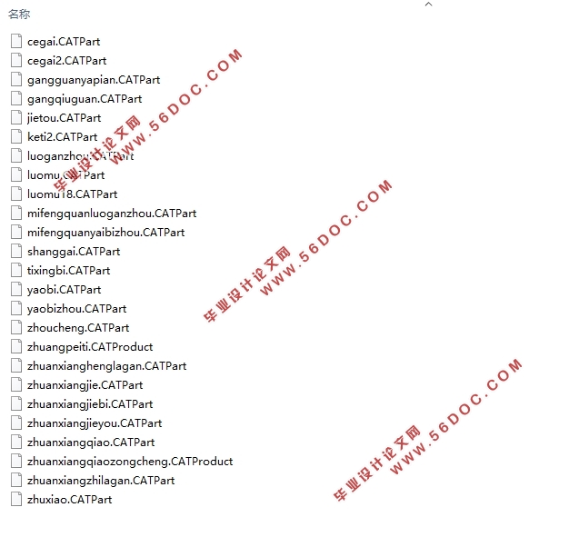
5.4转向器的三维模型装配 31
总结 33
参考文献 34
致谢 36
|