经济型轿车制动系统分析计算与浮钳盘式制动器设计(含CAD图,CATIA三维图)(论文说明书16400字,CAD图12张,CATIA三维图)
摘要
本文以浮钳盘式制动器为研究对象,介绍了浮钳盘式制动器的研究意义、发展现状以及制动器的结构原理,并且对浮钳盘式制动器的相关参数进行了设计计算,同时对制动器的零部件进行了有限元分析。
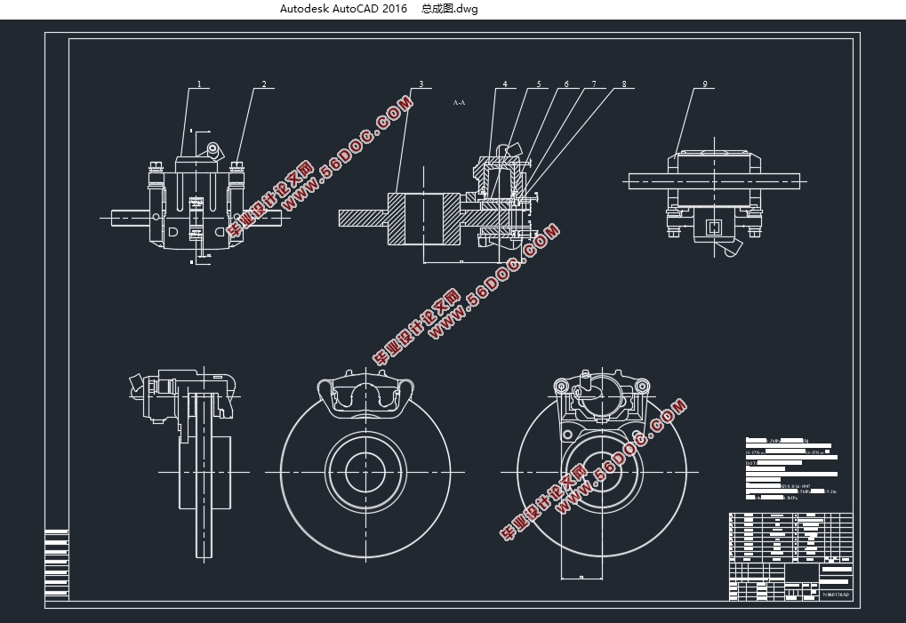
浮钳盘式制动器设计计算。根据整车参数和查阅资料、实验总结选定了路面附着系数及同步附着系数,依据该型号客车的前后轴载荷、中心高度及制动减速度进行制动系统的匹配计算(前、后轴制动力分配等),最大制动力矩的确定。在汽车的总布置参数及汽车制动系统各部件的结构形式、匹配关系确定之后,通过参考已有的同等级汽车的同类制动器,初选制动器的主要部件的主要参数,并据以进行前轮浮钳盘式制动器各部件结构的初步设计,然后进行各项制动性能的计算、分析、评价。根据计算分析结果对设计参数进行必要的修正,使得制动器各零部件的结构规格满足基本性能参数,最后完成各零件的设计,包括制动钳体、活塞、制动盘、和摩擦衬块等。之后根据有关零件的材料、尺寸和性能指标,对制动力矩、制动衬块的摩擦系数以及制动衬块摩损特性进行校核计算,以确认盘式制动器是否达到设计性能要求。
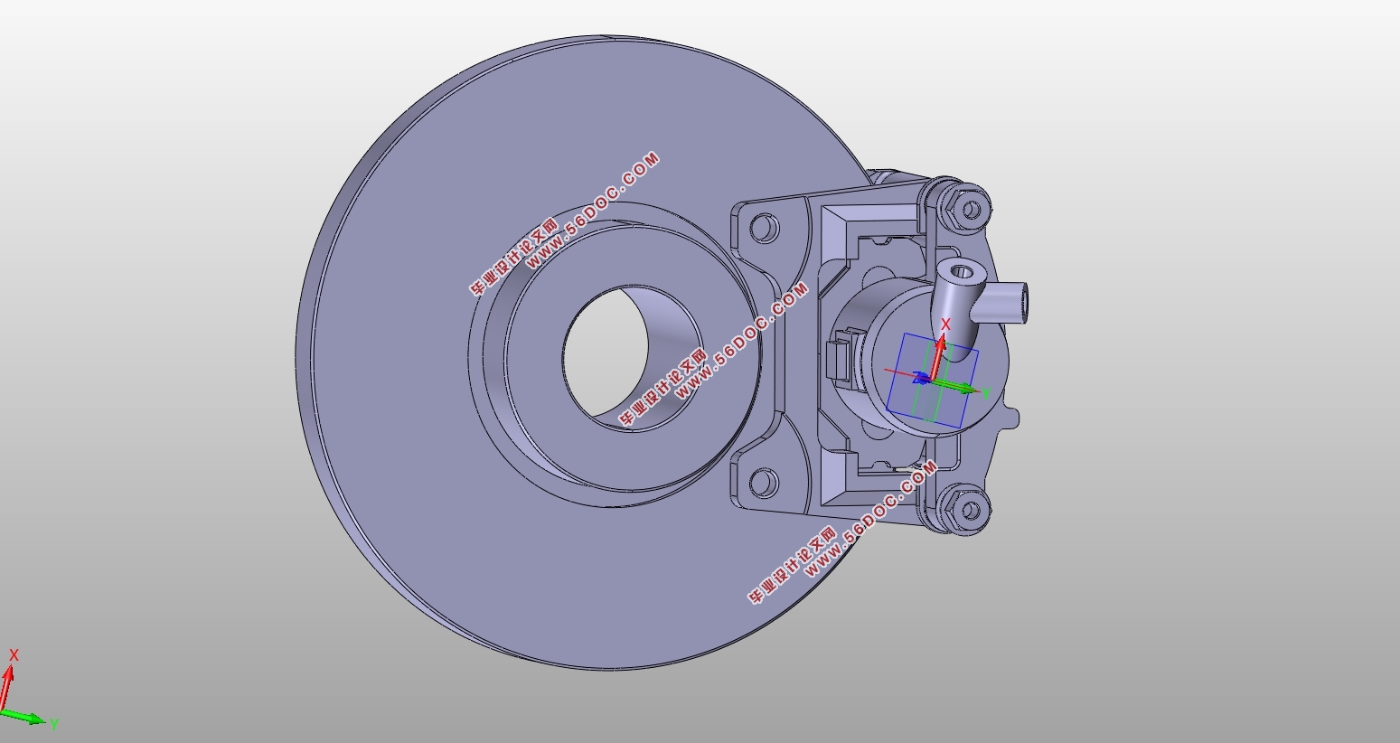
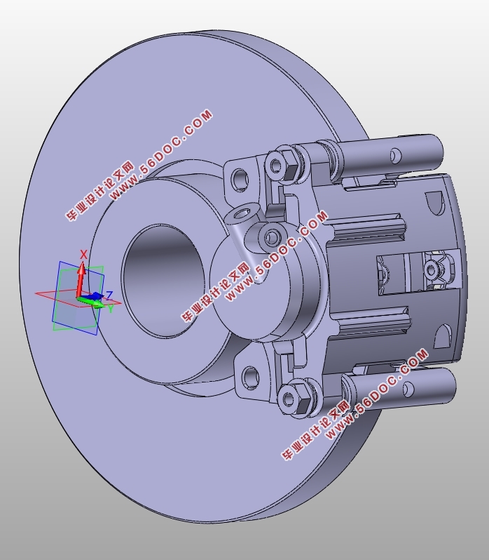
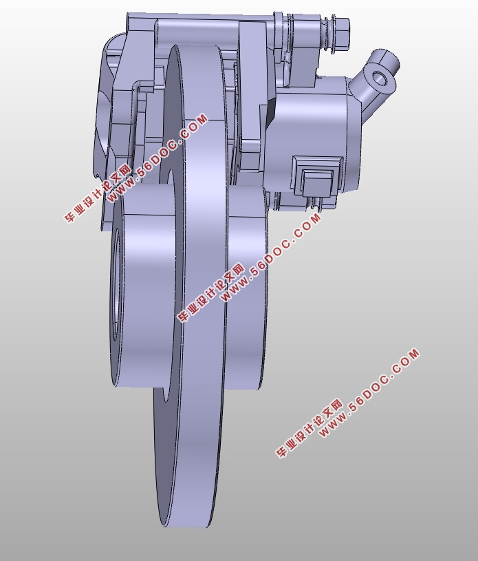
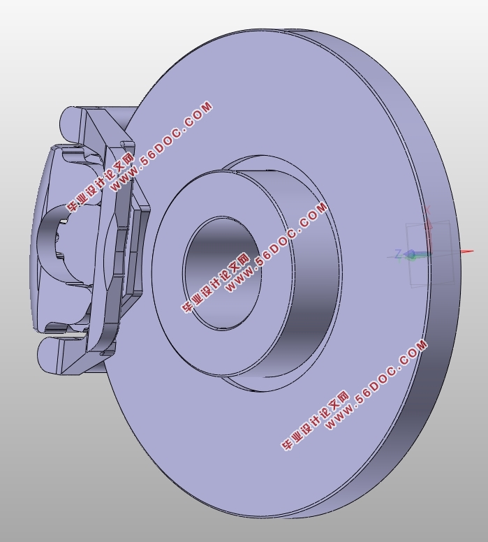
CATIA三维建模。根据理论计算得到的主要性能尺寸参数,采用CATIA软件绘制出浮钳盘式制动器相关零件的三维模型与装配模型,包括活塞、制动钳钳体、制动盘以及制动钳支架等的建模和装配过程。
浮钳盘式制动器零部件有限元模型建立及分析。将CATIA建好的三维模型导入ansys中,利用ansys中的workbench来对制动器的主要零件(制动钳钳体、活塞以及制动钳支架)进行有限元分析。该过程包括对制动钳钳体、活塞以及制动钳支架进行网格的划分、载荷的加载、相关约束的添加以及迭代求解,得到了该零件在工作状态下的应力应变云图。观察零件在工作中的具体应力分布,得出零件中最大应力区域和最小应力区域,并把仿真计算结果与零件材料的抗拉强度与屈服强度进行比较。通过分析结果对零件结构进行优化设计,加强了最大应力部分的结构强度,同时减少了小应力部分的厚度,节省了材料。最后的仿真结果表明其满足强度设计要求,证明该浮钳盘式制动器的设计是合理的。
关键字:浮钳盘式制动器 CATIA 有限元分析
Abstract
In this paper, the floating caliper disc brake is designed. The significance and development status of the floating caliper disc brake and the structural principle of the brake are described, and the relevant parameters of floating caliper disc brake is calculated, and the finite element analysis of the brake parts is done at last.
Design calculations of floating caliper disc brake. According to the vehicle parameters and access to information, experiments summarized selects road adhesion coefficient and simultaneous attachment coefficient. And we do matching calculation (front, rear axle system power distribution, etc.) to determine the maximum braking torque based on the model's front and rear axle load buses, center height and braking deceleration braking system. After the general arrangement in the automotive brake system parameters, components of the structure and matching relationship being determined, by reference to the same level of existing similar car brakes, main parameters of the main components of brake is primary selected, and we do preliminary design of the various components structure of the front floating caliper disc brakes. Then the braking performance calculation, analysis and evaluation is done. According to the results of calculation and analysis, we are necessary to correct the design parameters so that the structure of the various components of brake to meet the basic performance parameters and finalize the design of the parts, including brake calipers, pistons, brake disc, and friction pads and so on. After according to the material, size and performance indicators of the relevant parts, we check brake torque, brake pad brake pad friction coefficient and wear characteristics to confirm whether the disc brake design performance requirements is right.
Three-dimensional CATIA models. According to the main performance dimensions of theoretical calculations, we use CATIA software to draw out the three-dimensional model of the floating caliper disc brake related parts and assembly models, including pistons, brake caliper calipers, brake discs and brake caliper brackets modeling and assembly process.
The finite element modeling and analysis of floating caliper disc brake parts. The three-dimensional model is built into CATIA ansys, and we use workbench of ansys to do the finite element analysis for the main parts of the brake (brake caliper caliper body, piston and the brake caliper bracket). This process includes brake caliper caliper body, piston and brake caliper bracket for meshing, load loading, related add constraint and iterative solution and we got the stress and strain contours of the part in the work. Observing the specific stress distribution of parts in the work , we obtain and the minimum stress and maximum stress regions in the part and the simulation results are compared with the tensile strength and yield strength of the material. By analyzing the results, the structure design of the part is optimized. We strengthen the structural strength of the maximum stress of the part, reducing the thickness of the portion of small stress and saving material at the same time. The simulation results show that it meets the requirements of strength design, showing that the floating caliper disc brake is designed to be reasonable.
Keywords: floating caliper disc brake; CATIA; finite element analysis
本次设计整车基本参数如下:
(1) 整车最大总质量:满载1470kg 空载970 kg
(2) 轴距:2443mm
(3)轮胎规格:155R13
(4) 最高车速:170km/h
(5) 前轴载荷:满载733 kg 空载597 kg
(6) 后轴载荷:满载737 kg 空载373 kg
(7) 整车重心高:满载515 mm 空载510 mm
(8)制动踏板比:5.2
在汽车的总布置参数及汽车制动系统各部件的结构形式,匹配关系确定之后,即可参考已有的同等级的汽车的同类制动系统,初选制动系统的主要部件的主要参数,并据以进行各部件结构的初步设计,然后进行各项制动性能的计算、分析、评价。根据计算分析结果对设计参数进行必要的修正,直到基本性能参数满足要求为止。
目录
摘要 I
Abstract II
第1章 绪论 1
1.1 研究目的与意义 1
1.2 国内外研究现状 1
1.2.1 国内研究现状 2
1.2.2 国外研究现状 2
1.3 主要研究内容 3
1.4浮钳盘式制动器概述 3
1.4.1浮钳盘式制动器的结构及其原理 3
1.4.2浮钳盘式制动器的优点 4
第2章 浮钳盘式制动器的设计计算 5
2.1 汽车液压制动系统概述 5
2.2 汽车液压制动系统设计分解模型 7
2.3 制动器设计计算 8
2.3.1 汽车前后车轮制动力理想分配设计计算原理 9
2.4 汽车最大减速度下制动力矩设计计算原理 12
2.5盘式制动器参数设计基本原理 13
2.6 盘式制动器校核计算 16
第3章 浮钳盘式制动器三维模型建立 19
3.1 软件介绍 19
3.2 浮钳盘式制动器零部件三维建模 20
3.2.1 钳体 20
3.2.2 活塞 22
3.2.3 摩擦衬块 23
3.2.4 摩擦衬块底板 24
3.2.5 制动盘 26
3.3 装配 27
3.3.1钳体与支架装配 28
3.3.2 活塞与钳体装配 28
3.3.3 摩擦衬块总成装配 28
3.3.4 总成装配 29
3.3.5爆炸图 30
3.4 本章小结 31
第4章 浮钳盘式制动器零部件有限元分析 32
4.1软件介绍 32
4.2 网格化分 33
4.3材料属性设置 34
4.4载荷与约束设置 34
4.5结果分析 35
4.6本章小结 37
第5章 总结与展望 38
5.1 总结 38
5.2 展望 38
参考文献 39
致谢 41
|