福田奥铃中型货车驱动桥设计(含CAD零件图装配图)(英文版)
来源:56doc.com 资料编号:5D22493 资料等级:★★★★★ %E8%B5%84%E6%96%99%E7%BC%96%E5%8F%B7%EF%BC%9A5D22493
资料以网页介绍的为准,下载后不会有水印.资料仅供学习参考之用. 密 保 惠 帮助
资料介绍
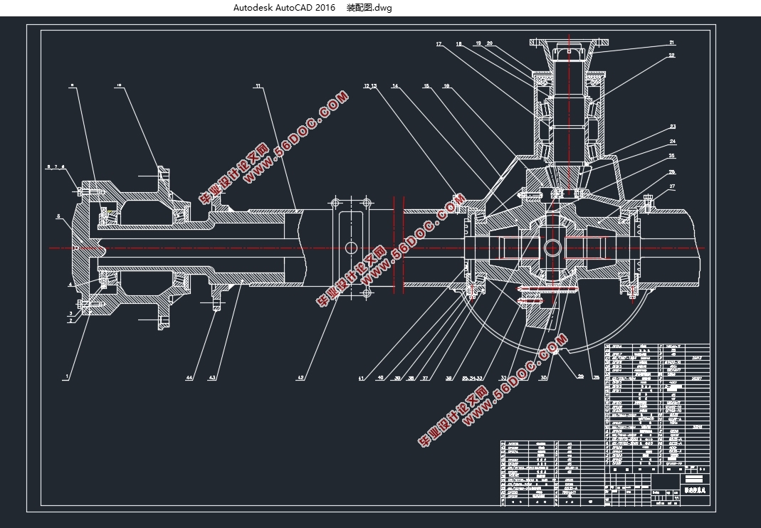
福田奥铃中型货车驱动桥设计(含CAD零件图装配图)(英文版)(任务书,开题报告,文献摘要,论文说明书英文版10000字,CAD图5张)
Design of drive axle in medium truck of Foton Aoling
摘要
本次设计是中型货车驱动桥的设计,驱动桥是汽车传动系统的重要部分,位于驱动链的末端,它的作用是提高转矩并将转矩传递到车轮和实现两车轮的差速功能.驱动桥作为汽车四大总成之一,它的性能的好坏直接影响整车性能,而对于载重汽车显得尤为重要.当采用大功率发动机输出大的转矩以满足目前载重汽车的快速、重载的高效率、高效益的需要时,必须要搭配一个高效、可靠的驱动桥.
关键字:载重汽车驱动桥单级减速桥弧齿锥齿轮
Abstract
This is the design of the medium truck drive axle. The drive axle is an important component of the automotive transmission system, located at the end of the drive train.Its function is to increase the transmission shaft or transmission torque, passing it to the drive wheel and making it have a differential function. Driving axle as one of the four major assembly car, its performance is a direct impact on vehicle performance, for the truck is particularly important. Using high-power engine output torque to meet the current fast, heavy load of high-efficiency, high efficiency needs,which must be with a highly efficient and reliable drive axle.
Key Words:medium truck;drive axle;single final drive final drive;the spiral bevel gear


Contents
摘要 1
Chapter1 Introduction 4
Chapter2 Type and arrangement of drive axle structure 6
2.1 Rigid drive axle 6
2.2 divided axle 6
2.3 Multiaxle drive 7
Chapter3 Final drive design 10
3.1The structure of the Final drive 10
3.1.1The gear type of the Final drive 10
3.1.2Deceleration of the Final drive 10
3.1.3 Final drive and driven bevel gear support form 10
3.2Selection and Design of Basic Parameters of final drive 11
3.2.1Determination of driveaxle ratio 11
3.2.2 The loadcalculatedon Final drive 12
3.2.2Selection of basic parameters of Final drive 13
3.2.2.1 Driving and driven bevel gear teeth and 13
3.2.2.2 Large end diameters and face modulus of Driving bevel gears 13
3.2.2.3Selection of tooth width F of spiral bevel gear 14
3.2.2.4Midpoint helical angle 14
3.2.2.5 Spiral direction 14
3.2.2.6 Normal pressure angle 14
3.2.3Calculation of geometric dimensions of circular bevel gears for Final drive 15
3.2.5 Strength Calculation of Spiral Bevel Gear of Arc Gear of Final drive 17
3.2.5.1 Gear damage form and life 17
3.2.5.2The circumferential force on the gear length of the main gear unit 19
3.2.5.3Calculation of Bending Strength of Final drive Gear 19
3.2.5.4Calculation of gear surface contact strength of gear 20
3.2.6Materials and Heat Treatment of Final drive Gear 21
3.2.6.1 Calculation of Final drive bearings 21
3.2.6.2Calculation of bearing load of Final drive 23
Chapter4 Differential design 27
4.1Selection of differential structure type 27
4.2 Design of Symmetrical Cone Planetary Pinion Differential 27
4.2.1Selection of Basic Parameters of Differential Gear 27
4.2.1.1The choice of the number of differential gears 27
4.2.1.2Determination of Spherical Radius of Planetary Pinion 27
4.2.1.3Selection of Gear Number of Planetary Pinion and Axle Gear 28
4.2.1.4The timing of the differential bevel gear is determined 28
4.2.2Geometric Calculation of Differential Gear 29
4.3.3Strength Calculation of Differential Gear 31
Chapter5 Design of the axle shaft 33
5.1Determination of Loads for full floating axle shaft 33
5.2The primary selection of the diameter of the shaft of the full floating axle shaft 34
5.3Strength calculation of full floating axle shaft 34
5.4Strength calculation of axle shaft spline 35
Chapter6 Design of axle housing 36
6.1 Structure type of axle housing 36
6.2 Force Analysis and Strength Calculation of axle housing 37
6.2.1 Static bending stress calculation of axle housing 37
6.2.2 Calculation of axle housing strength under load impacted impinging road surface 38
6.2.3 Calculation of axle housing strength in maximum driving traction 39
Conclusion 41
Acknowledgement 42
Reference 43
|


