新能源汽车盘式制动系统设计(含CAXA图,CATIA三维图)
来源:56doc.com 资料编号:5D22597 资料等级:★★★★★ %E8%B5%84%E6%96%99%E7%BC%96%E5%8F%B7%EF%BC%9A5D22597
资料以网页介绍的为准,下载后不会有水印.资料仅供学习参考之用. 密 保 惠 帮助
资料介绍
新能源汽车盘式制动系统设计(含CAXA图,CATIA三维图)(任务书,开题报告,论文说明书15000字,CAXA图10张,PDF图10张,CATIA三维图)
摘要
传统燃油车辆对石油的依赖以及排放的大量有害气体堪忧,发展新能源汽车已经势在必行。
在发展新能源汽车的同时,原始制动系统也需要做相应更改。受当下技术条件及研发成本的限制,对原有制动系统进行改进使其适用于新能源汽车是现阶段比较可行的办法。本文基于“改进”思路对一款纯电动汽车制动系统进行设计。除了传统的液压制动器,新能源汽车的制动系统还包括能量再生制动,本文对典型的控制策略进行了比较和分析,并选择了并行制动能量回收控制策略来分配制动力;液压制动方面采用智能助力器iBooster替代原有的真空泵实现助力并更好地实现制动能量回收。
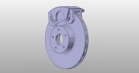
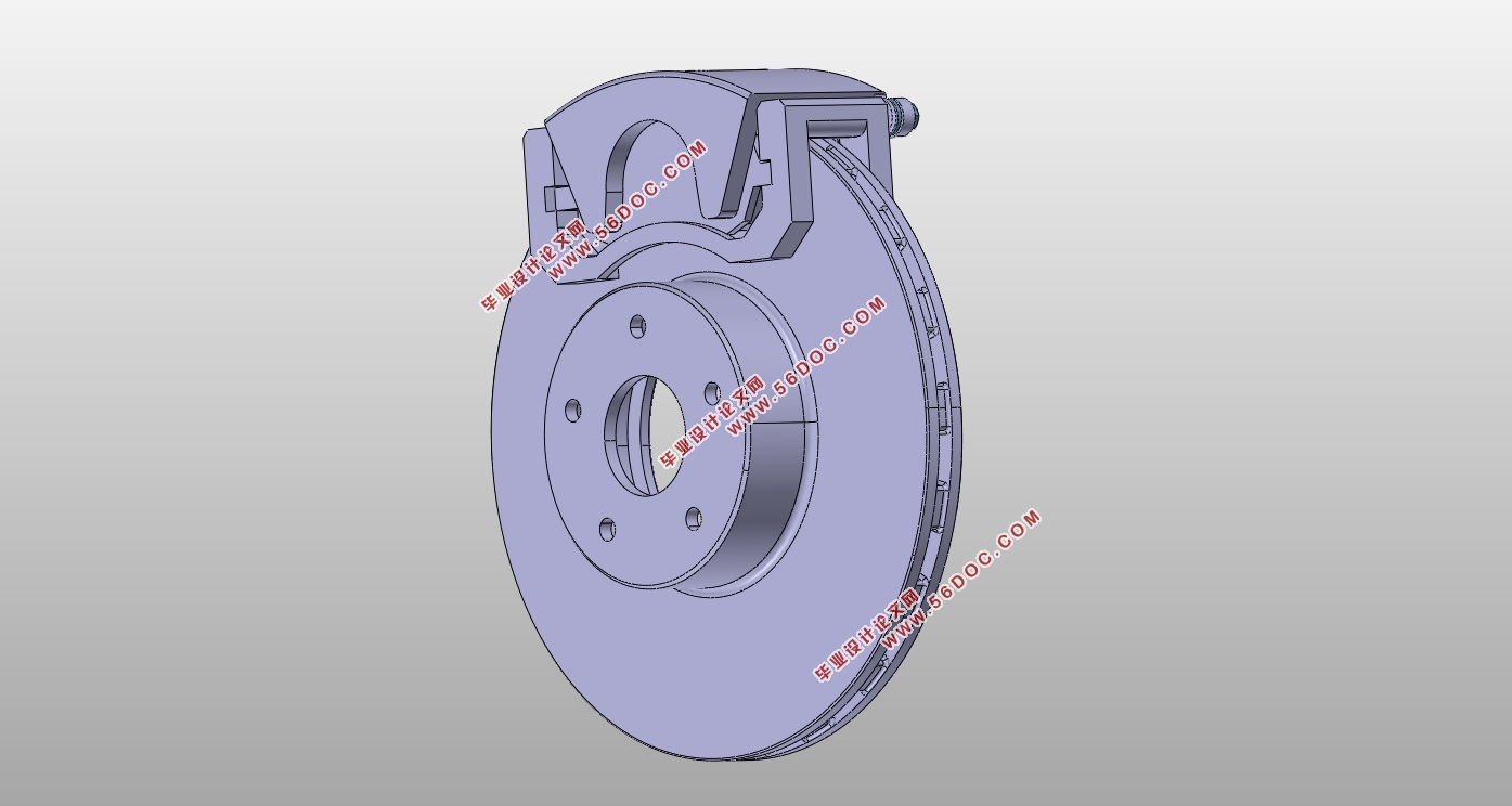
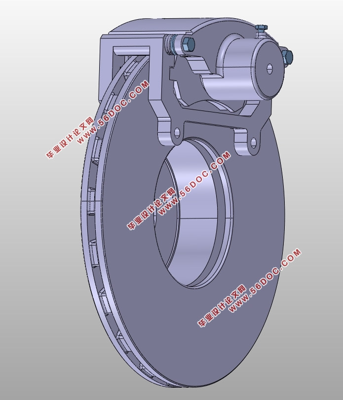
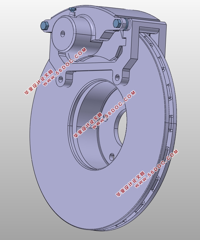
此次设计中,前后制动器均设计为浮动卡钳盘式,其中前轮采用通风盘,后轮用实心盘;制动驱动机构设计为简单人力液压型,双回路制动管路呈X型布置。最后做制动系统的性能验算,并利用MATLAB绘制制动力分配线及利用附着系数曲线判断法规的符合性,使用CATIA建模和组装制动部件,利用caxa CAD绘制各零件的二维工程图及制动系统的结构图。
关键词:新能源汽车;制动;iBooster;钳盘式制动器
Abstract
The dependence of traditional fuel vehicles on oil and the large amount of harmful gases emitted are worrying. It is imperative to develop new energy vehicles.
At the same time as the development of new energy vehicles, the original brake system needs to be changed accordingly. Due to the current technical conditions and research and development costs, it is a feasible method to improve the original braking system to make it suitable for new energy vehicles. This paper designs a pure electric vehicle brake system based on the "improvement" idea. In addition to the traditional hydraulic brakes, the braking system of the new energy vehicle also includes energy regenerative braking. This paper compares and analyzes the typical control strategy, and selects the parallel braking energy recovery control strategy to distribute the braking force; hydraulic braking In terms of the use of the intelligent booster iBooster instead of the original vacuum pump to achieve assistance and better achieve braking energy recovery.
In this design, the front and rear brakes are designed as floating caliper discs, in which the front wheel adopts a ventilated disc and the rear wheel uses a solid disc; the brake drive mechanism is designed as a simple manual hydraulic type, and the double-circuit brake line is arranged in an X-shape. Finally, the performance verification of the brake system is performed, and the brake force distribution line is drawn by MATLAB and the compliance coefficient is judged by the adhesion coefficient curve. The CATIA is used to model and assemble the brake components. Using caxa CAD to draw the 2D drawings of the various parts and the structural diagram of the brake system.
Key Words:new energy vehicles;brake;iBooster;clamp disc brake
目录
第一章绪论 1
1.1 汽车制动技术研究现状 1
1.2选题背景及意义 1
1.3 制动系统概述 2
1.3.1 制动系统的功能 2
1.3.2制动系统的组成与分类 2
1.3.3制动系统的设计要求 2
1.4 本文主要工作与研究内容 3
第二章新能源汽车制动系统设计方案确定 4
2.1 新能源汽车制动系统与传统能源汽车制动系统的异同 4
2.2 新能源汽车制动系统总体方案确定 4
2.2.1 液压制动助力方案选择 4
2.2.2 再生制动前后轴制动力分配控制策略选择 5
2.3 制动器结构型式分析与选择 7
2.3.1 鼓式制动器 8
2.3.2 盘式制动器 8
2.4 制动驱动机构型式选择 9
2.4.1 简单制动系 9
2.4.2 动力制动系 9
2.4.3 伺服制动系 9
2.5 分路系统型式选择 9
2.5.1 II型回路 9
2.5.2 X型回路 10
2.5.3 其他类型回路 10
第三章制动系统主要参数确定 11
3.1 参考车型制动系相关主要参数值 11
3.2 同步附着系数 的确定 12
3.3 前后轮制动力分配系数的确定 13
3.4 地面对前、后车轮的法向反作用力 13
3.5 制动器最大制动力矩的确定 14
3.6 应急制动和驻车制动的制动力矩 14
3.6.1 应急制动 14
3.6.2 驻车制动 16
3.7 制动效能因数 17
第四章浮钳盘式制动器结构设计计算 19
4.1 盘式制动器主要元件结构设计 19
4.1.1 制动盘 19
4.1.2 制动钳 19
4.1.3 制动块 20
4.2 主要参数确定 21
4.2.1 制动盘直径 21
4.2.2 制动盘厚度 21
4.2.3 摩擦衬块外半径 与内半径 21
4.2.4 制动衬块工作面积 22
4.3 磨损性能验算 22
第五章液压制动驱动机构设计计算 24
5.1 制动轮缸直径确定 24
5.1.1 前制动轮缸直径确定 24
5.1.2 后制动轮缸直径确定 24
5.2 制动主缸直径确定 25
5.3 制动踏板力 26
5.4制动踏板工作行程 26
第六章制动系统性能验算 27
6.1 制动性能评价及分析 27
6.2 制动器制动力分配曲线分析 27
6.3 利用附着系数与制动强度 28
6.4 前后制动器制动力分配的要求 28
6.4.1 ECE制动法规 28
6.4.2 制动力分配调节 29
6.5 制动减速度与制动距离计算 29
第七章总结 31
参考文献 31
致谢 33
|