新能源汽车轮毂电驱动系统结构设计(含CAD零件装配图)(任务书,开题报告,外文翻译,论文说明书13000字,CAD图8张)
摘要
随着环境和能源问题的日益严重,而传统内燃机汽车又是能源消耗与污染排放大户,因此发展新能源汽车势在必行。轮毂电机驱动汽车由于其与汽车轮毂集成驱动车轮,省去了传统传动机构,是一种有广阔前景的电动汽车驱动方案。
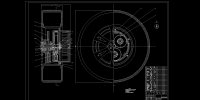
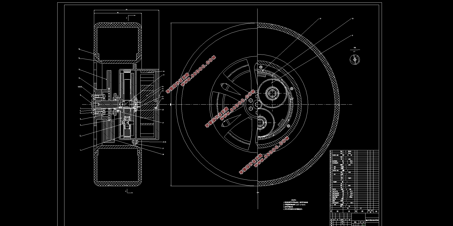
本设计在学习总结国内外轮毂电驱动发展成果的基础上,在对比分析了多种传动方案的基础上选择了内转子轮毂电机加一级NGW型行星齿轮减速器的方式进行驱动方案的集成设计。动力从电机传递到和太阳轮做成齿轮轴的输入轴,通过太阳轮和固定在机体上的齿圈与行星轮啮合,经减速增扭后由行星架输出动力到车轮。
首先根据目标车辆性能要求选择电机,然后选择满足运动要求的传动比进行行星齿轮减速器的配齿计算。根据齿轮齿根弯曲应力初算模数,并初算各齿轮尺寸参数并对齿轮进行了详细的校核。
然后对行星齿轮减速器的各零部件及其支承进行了设计计算,合理选用了均载机构使各行星轮承载均匀。再运用CATIA软件完成各零部件三维模型建立并进行装配,在此基础上进行机构的运动仿真,验证机构按预期运动。
内转子轮毂电机加减速器的驱动方案在乘用车上还未能完成量产,本设计对其进行尝试,以期有一定参考意义。
关键词:电动汽车轮毂电驱动系统行星齿轮减速器CATIA建模
Abstract
With the increasingly serious environmental pollution and energy crisis, the traditional internal combustion engine vehicles are the major sources of energy consumption and exhaust emissions, thus it is imperative to develop new energy vehicles. The hub motor drives the car with hub motor integrated with the wheel, eliminating the traditional transmission mechanism, and is a promising electric vehicle drive solution.
On the basis of learning and summarizing the development results of domestic and foreign wheel hub electric drive, this design selects the internal rotor hub motor and the first-stage NGW planetary gear reducer to design the drive scheme based on the comparison of various transmission schemes. The power is transmitted from the motor to the input shaft, and meshes with the planetary gear through the sun gear and the fixed ring gear. After being decelerated and twisted, the planet carrier outputs power to the wheel.
First, select the motor according to the target vehicle performance requirements, and then select the gear ratio that meets the motion requirements to calculate the gear of the planetary gear reducer. According to the initial calculation modulus of the gear root bending stress, the gear size parameters are calculated first and the gears are checked in detail.
Then the design and calculation of the various components and their support of the planetary gear reducer are carried out, and the uniform load mechanism is used to make the bearing of each planetary wheel uniform. Then use CATIA software to complete the 3D model of each component and assemble it. On this basis, the motion simulation of the mechanism is carried out to verify that the mechanism works as expected.
The driving scheme of the inner rotor hub motor acceleration and deceleration has not yet been mass-produced on the passenger car. This design has been tried for a certain reference.
Keywords: electric vehicle, hub electric drive system, planetary gear reducer, CATIA modeling
1.3.1设计方向
本文主要研究轮毂驱动系统的传动机构设计,希望在轮毂电机减速驱动机构的设计计算方面有一定参考意义。拟采用减速驱动型电动轮,减速器理论上可选择变速比齿轮减速器,也可以采用固定速比齿轮减速器。可变速比减速机构由于结构比较复杂,需要占用较大的空间,同时成本较高,不利于作为轮毂驱动减速方式。目前,电动车一般采用固定速比变速器作为减速装置。减速器将动力从轮毂驱动电机直接传递给车轮,起到降低转速、增加转矩的功能。由于行星齿轮具有减速比大,结构紧凑的优点,易于布置,本设计采用行星齿轮机构作为减速机构,对其结构及相应尺寸进行设计计算,让其满足尺寸和性能要求。
1.3.2设计基本内容
(1)分析轮毂电驱动系统及其部件的结构型式
(2)确定轮毂电驱动系统及其部件的结构设计方案
(3)轮毂电驱动系统及其部件的设计计算分析
(4)绘制轮毂电驱动系统装配图和主要零部件图
(5)轮毂电驱动系统运动学分析
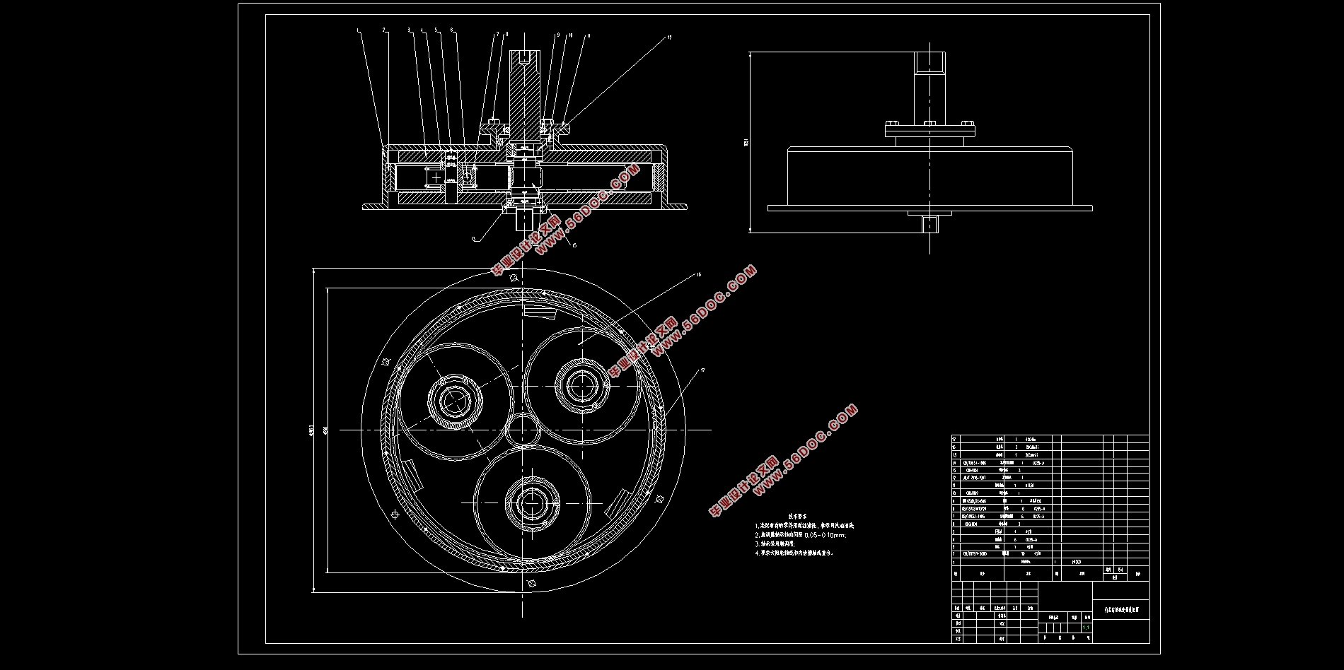
在本设计中,假定目标车辆的主要参数如表3-1。
表3-1整车详细参数
车辆参数 数值
整车质量m(kg) 1200
空气阻力系数CD 0.35
迎风面积(m2) 2.6
滚动阻力系数f 0.02
轮毂尺寸(英寸) 14
旋转换算系数 1.02
最高车速(km/h) 120
0-100km/h加速时间(s) <10
最大爬坡度i(%) 30
目录
摘要 I
ABSTACT II
第1章 绪论 1
1.1课题背景 1
1.2国内外研究现状 1
1.3设计内容 2
1.3.1设计方向 2
1.3.2设计基本内容 3
第2章 轮毂减速器设计 4
2.1轮毂电驱动系统类型及选择 4
2.2轮毂减速器的传动方案 5
2.2.1轮毂减速器概述 5
2.2.2行星齿轮减速器选型 5
2.3本章小结 6
第3章 轮毂驱动的参数确定及关键零部件设计 7
3.1轮毂电机性能参数的确定 7
3.1.1整车性能要求 7
3.2.2驱动电机参数计算(四轮驱动) 7
3.2行星齿轮减速器主要零部件设计 9
3.2.1行星齿轮传动齿数分配应满足的条件 9
3.2.2齿轮受力分析和强度设计计算 10
3.2.3齿轮校核计算 15
3.3.4其他零部件的设计计算 20
3.3本章小结 24
第4章 行星齿轮传动结构的设计 25
4.1行星齿轮传动的均载机构 25
4.2轮毂电驱动系统的三维模型建立 26
4.2.1中心轮的结构设计及其支承设计 26
4.2.2行星轮的结构设计及其支承设计 27
4.3.3齿圈结构设计与固定 27
4.3.4转臂的结构设计 28
4.3.5装配设计 28
4.3本章小结 29
第5章 总结与展望 30
参考文献 31
致谢 32
|