小型电动代步车转向系统设计(含CAD零件图装配图,SolidWorks三维图)(任务书,开题报告英文,文献摘要,外文翻译,论文说明书19000字,CAD图4张,SolidWorks三维图)
摘要
转向系统是汽车中至关重要的一个系统,其性能的好坏将直接影响到汽车的操纵稳定性和驾驶员的驾驶感受。作为新兴的转向系统,电动助力转向系统相比于传统的转向系统,具有环保,节能,安全可靠等优点,而且其性能更加优越,能够充分调和传统转向系统无法解决的转向“轻”与“灵”的矛盾,是未来汽车转向系统的一个发展潮流。
本文首先阐述了汽车转向系统的发展历程,然后描述了传统转向系统对于当今时代的弊不足以及电动助力转向系统的优势,并分析了国内外对于电动助力转向系统的研究状况,并对电动助力转向系统的系统组成,工作原理以及其不同的类型作了简单的介绍。
通过运用计算软件MATLAB的优化设计,求解出了符合该车型的一个较为优化的转向梯形结构,并以转向梯形中齿条行程为基础,推算出了齿轮的具体参数。得到齿轮各个参数后,对齿轮进行了强度校核并对齿轮轴进行了安全验算。由此,确定了该转向系统的转向器以及转向梯形两个主要部分。随后,还对电动助力部分的电机进行了选型,并且选择了适合该车型的电动助力特性。
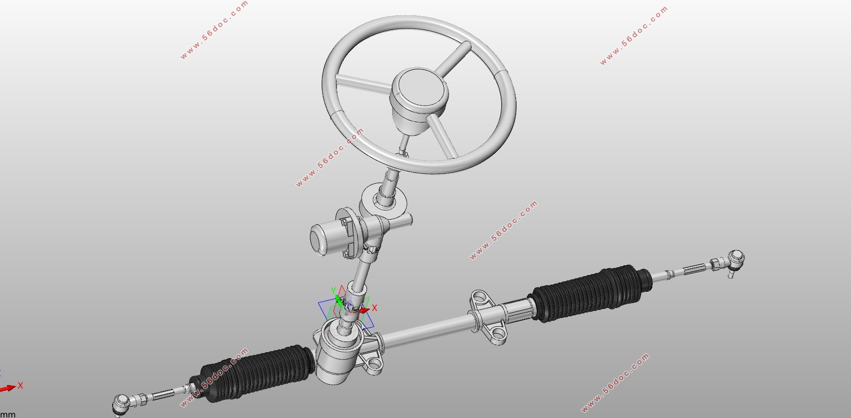
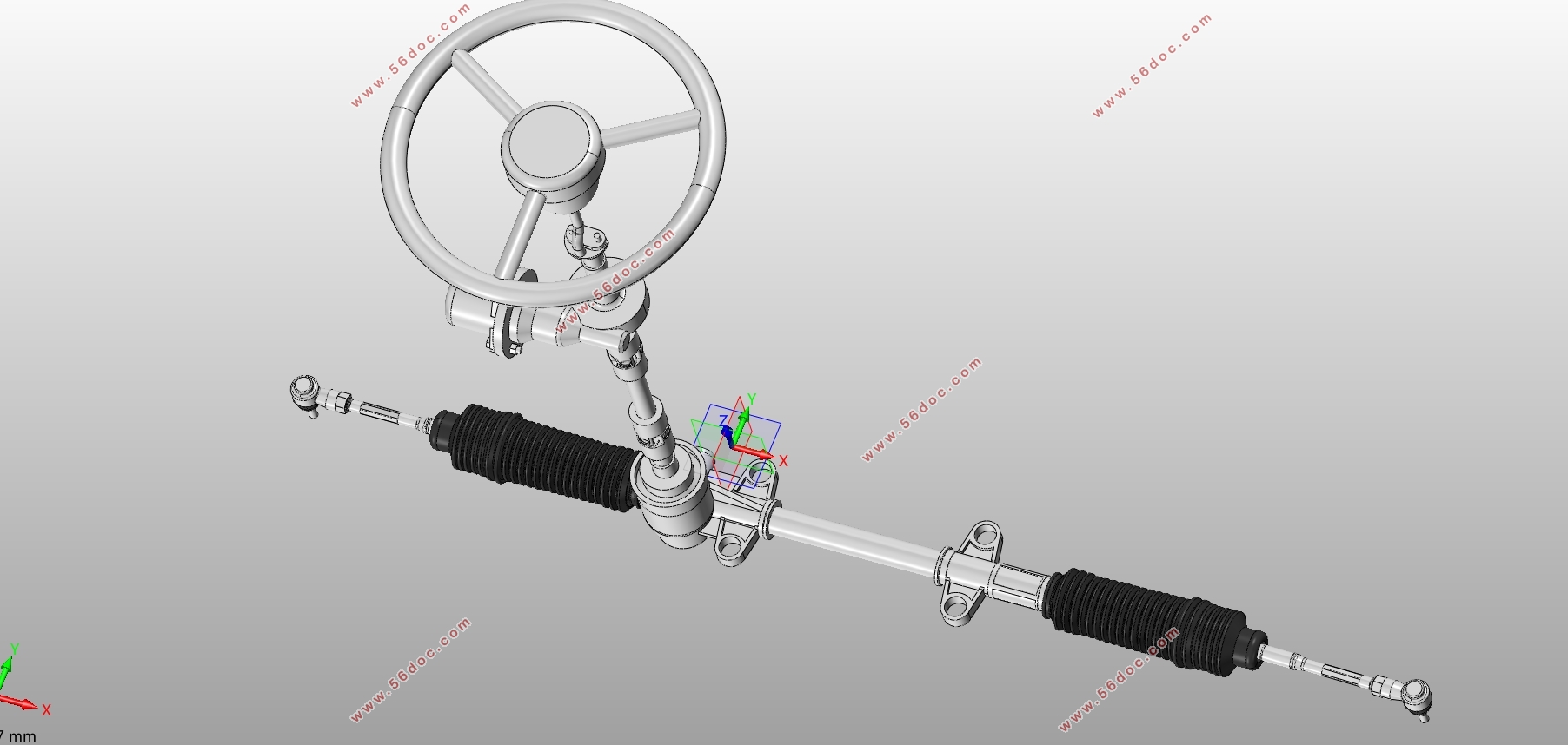
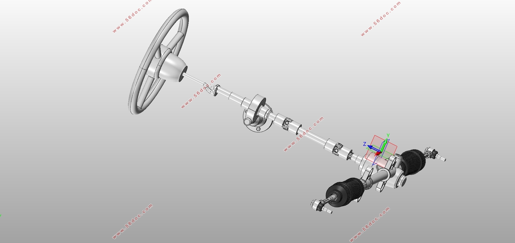
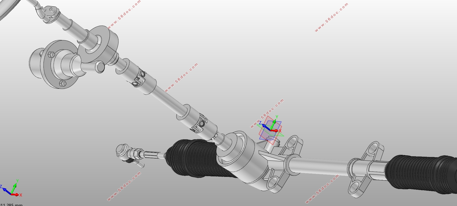
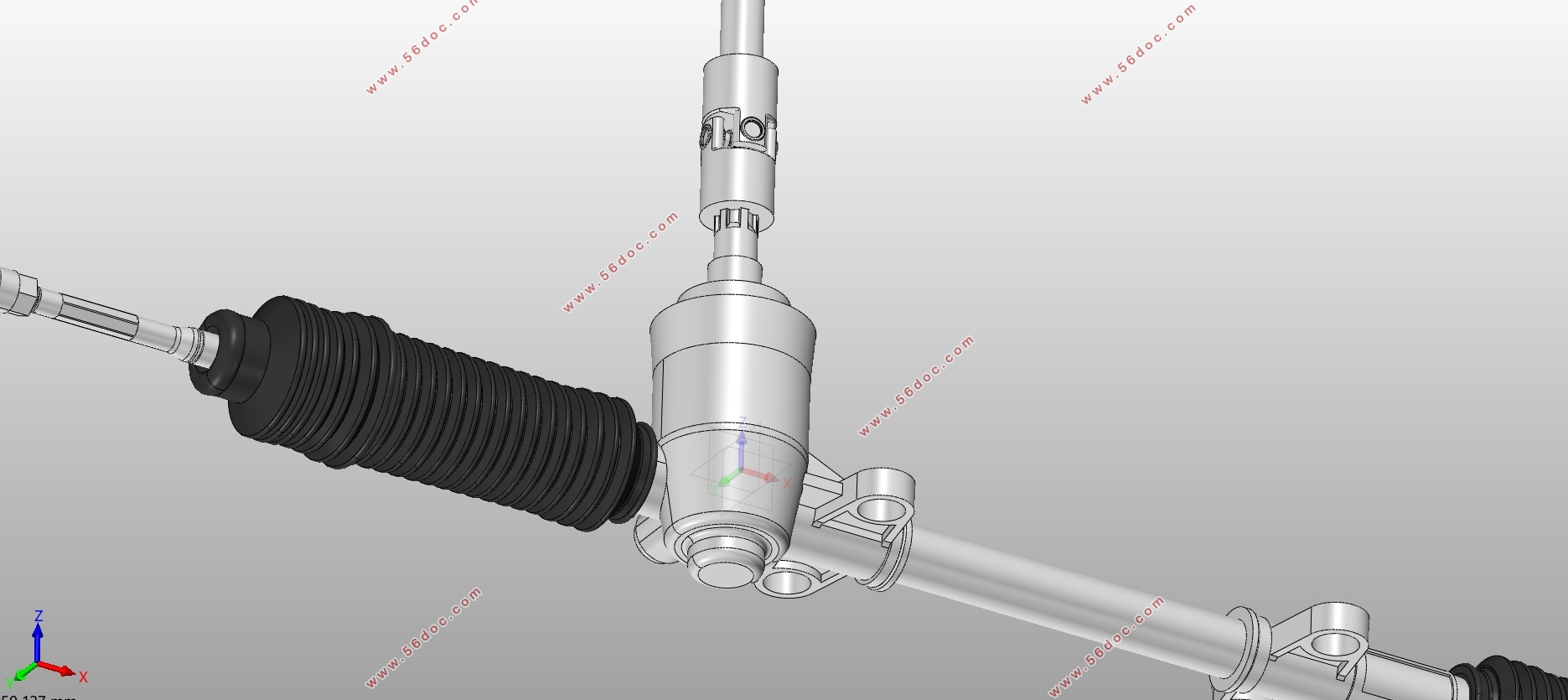
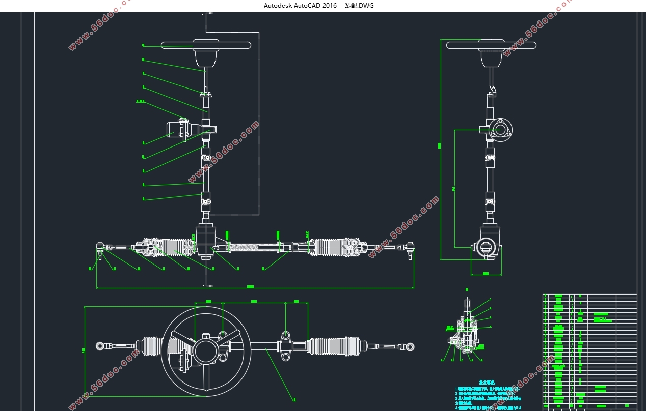
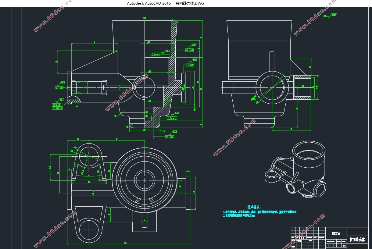
得出转向器具体参数和转向梯形参数后,基于三维建模软件Solid works对该转向系统进行了三维建模,其次还对转向系统中一些关键零部件,如齿轮轴和齿条,作了基于ANSYS Workbench的静力分析和模态分析。
关键词:电动助力转向系统;转向梯形;转向器;ANSYS Workbench
Abstract
Steering system is a vital system in vehicle. It will directly affect car's handling stability and driver's driving experience. As a new steering system, compare to the traditional steering system, it has the advantages of environmental protection, energy saving and safety. In addition, it can perfectly solve the contradiction between light and sensitive, so it will be a mainstream in the short future.
Firstly, this essay introduce the development history of vehicle steering system and discuss the drawback of traditional steering system as well as the advantages of electric power steering system(EPS). Moreover, it analyses the research status of both domestic and foreign. Then, this essay introduces the composition, working theory and types of EPS.
Secondly, through the optimization design of the calculation software MATLAB, a more suitable steering trapezoidal structure conforming to the model is solved, and the specific parameters of the gear are deduced based on the rack travel in the steering trapezoid. After processing the parameter of the gear, the gear and gear shaft are both been check for strength. Thus, the two main parts of the steering system are determined. Subsequently, the electric motor and the electric power characteristics motor was selected according to the vehicle.
After deriving the specific parameters of the steering gear and the trapezoidal, the steering system is modeled based on the 3D modeling software Solid works. Secondly, some key components such as gear shafts and racks in the steering system are made. Static Analysis and Modal Analysis are done through ANSYS Workbench.
Keyword: steering system; steering trapezoidal; steering gear; ANSYS Workbenc
1汽车参数
本次设计中需要用到的汽车参数如下表3.1所示
表3.1
项目 数值
整备质量 1000kg
满载质量 1360kg
整车长度 3500mm
整车宽度 1650mm
整车高度 1550mm
两主销间距离 1200mm
质心距前轴距离 2100mm
轴距 2500mm
前轮距 1440mm
后轮距 1440mm
前轮规格 165/65 R15
后轮规格 165/65 R15

目录
第一章绪论 1
1.1 引言 1
1.2电动转向系统国内外的研究现状 2
1.2.1 国外研究现状 2
1.2.1 国内研究现状 2
1.3 论文主要目的及意义 3
1.3.1 本文研究的目的及意义 3
1.3.2 本文研究的内容 3
第二章转向系统的选型 4
2.1电动助力转向系统组成与工作原理 4
2.2电动助力转向系统需要满足的要求 5
2.3 电动助力转向系统的类型及优点 5
2.4 选择合适的EPS 6
2.5 本章小结 6
第三章转向系统的计算 7
3.1 汽车参数 7
3.2 转向系主要性能参数的计算 7
3.2.1转向器正、逆效率的确定 7
3.2.2 转向系传动比的确定 7
3.2.3 转向器传动副传动间隙的确定 8
3.3 转向计算载荷的计算 8
3.4 转向梯形的计算 9
3.4.1 转向梯形的计算方法 9
3.4.2 运用MATLAB求解非线性规划问题的介绍 10
3.4.3 基于MATLAB的转向梯形优化设计 11
3.5 转向器的计算 14
3.5.1 转向齿轮计算 14
3.5.2 转向齿轮轴花键的计算 16
3.5.3 转向齿轮轴的计算 16
3.5.4 转向齿条的计算 22
3.6 电机的选择及减速机构的计算 22
3.6.1 对助力电机的要求 22
3.6.2 电机类型的选择 23
3.6.3 电机及减速机构参数的计算 23
3.7 电机助力特性的选择 25
3.8 本章小结 27
第四章转向系统模型建立 28
4.1 SOLIDWORKS的介绍 28
4.2 零件模型的建立 29
4.2.1 转向齿轮轴模型的建立 29
4.2.2 转向齿条的建模 30
4.2.3 转向器壳体的建模 30
4.2.4 转向横拉杆的建模 31
4.2.5 其余零件的建模 31
4.2.6 转向系统总装配 33
4.3 本章小结 33
第五章转向系统仿真分析 34
5.1 仿真模型的建立 34
5.2 划分网格与添加载荷,边界条件 34
5.2.1 齿轮轴划分网格与添加载荷,边界条件 34
5.2.2 齿条划分网格与添加载荷,边界条件 34
5.3 转向系统主要零件的静力分析 35
5.3.1 齿轮轴的静力分析 35
5.3.2 齿条的静力分析 37
5.4 转向系统主要零件的模态分析 39
5.4.1 齿轮轴模态分析 39
5.4.2 齿条的模态分析 41
5.5 本章小结 43
结论 44
1.本文工作总结 44
2.研究展望 44
参考文献 45
附录 46
致谢 48
|


