微型车前轮制动器设计(含CAD零件图装配图,CATIA三维图)(任务书,开题报告,文献摘要,外文翻译,论文说明书15000字,CAD图5张,CATIA三维图)
摘 要
我国作为世界上非常大的汽车市场,汽车的保有量相当大,其中微型车的数量特别庞大。随着汽车技术的发展,车辆行驶速度也越来越快,这样对汽车的安全性的要求就很高。在微型车保有量如此之大的情况下,设计出更加安全的微型车制动器就显得尤为重要。
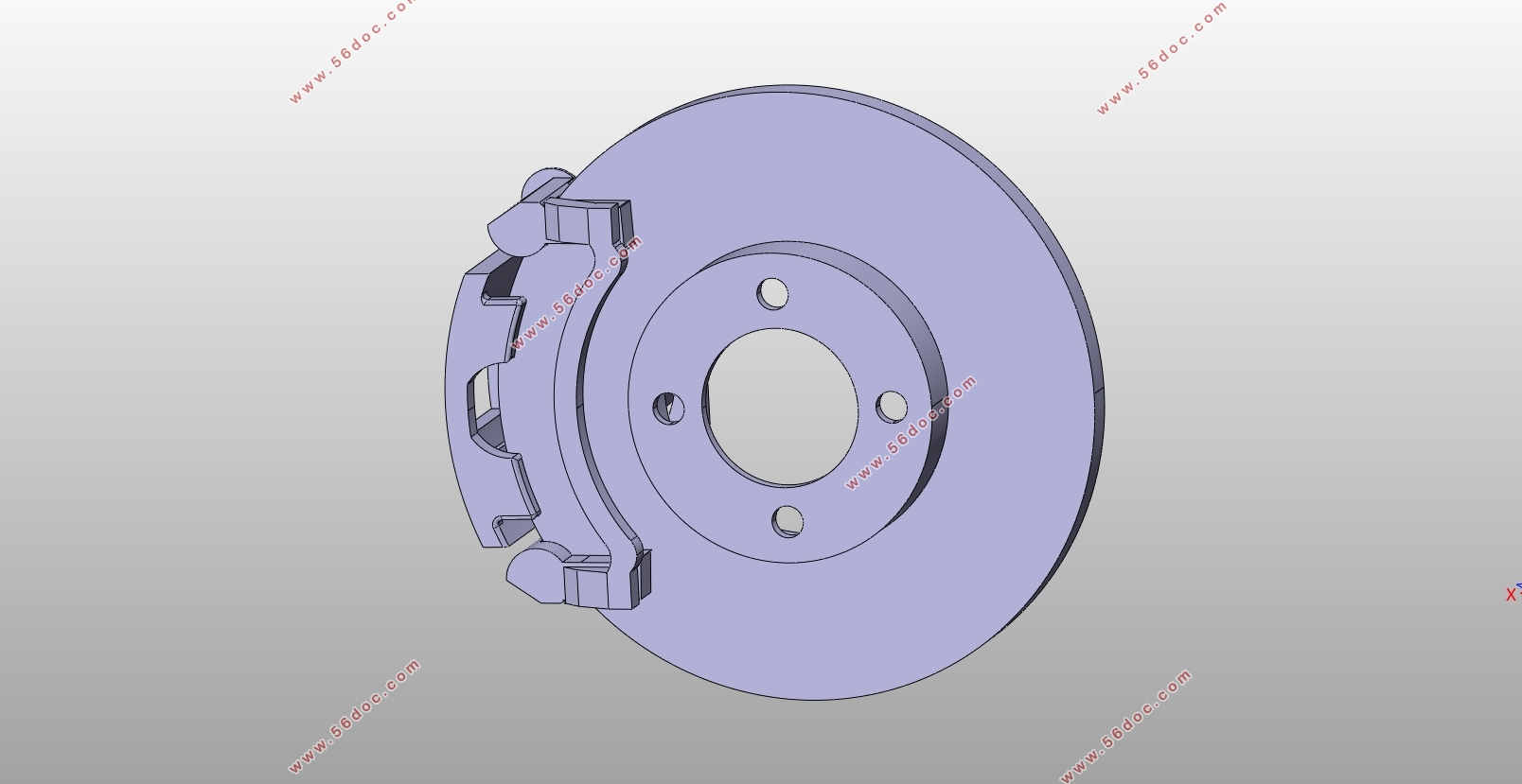
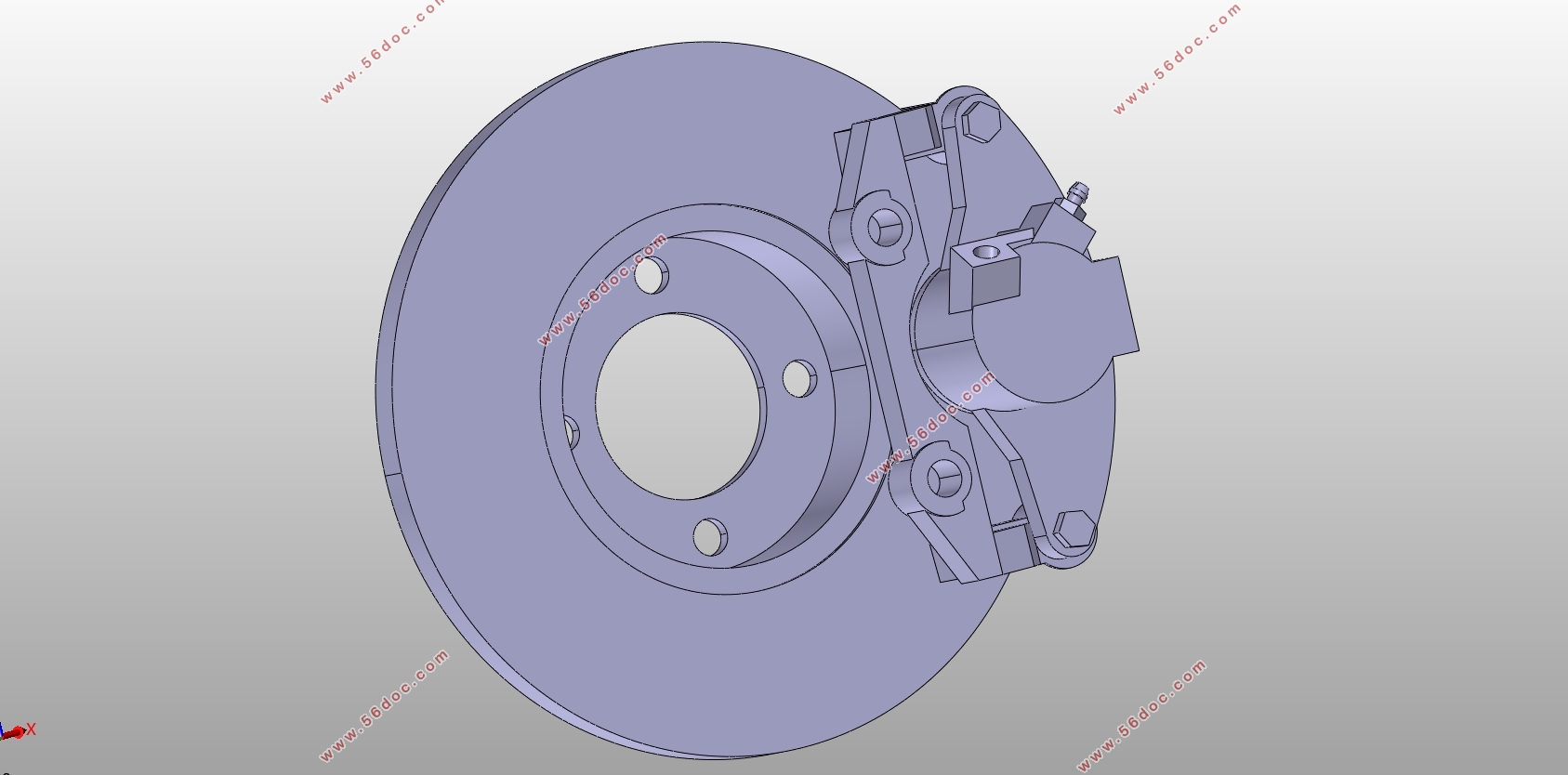
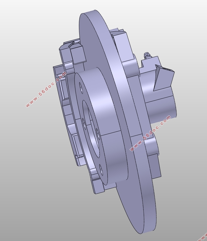
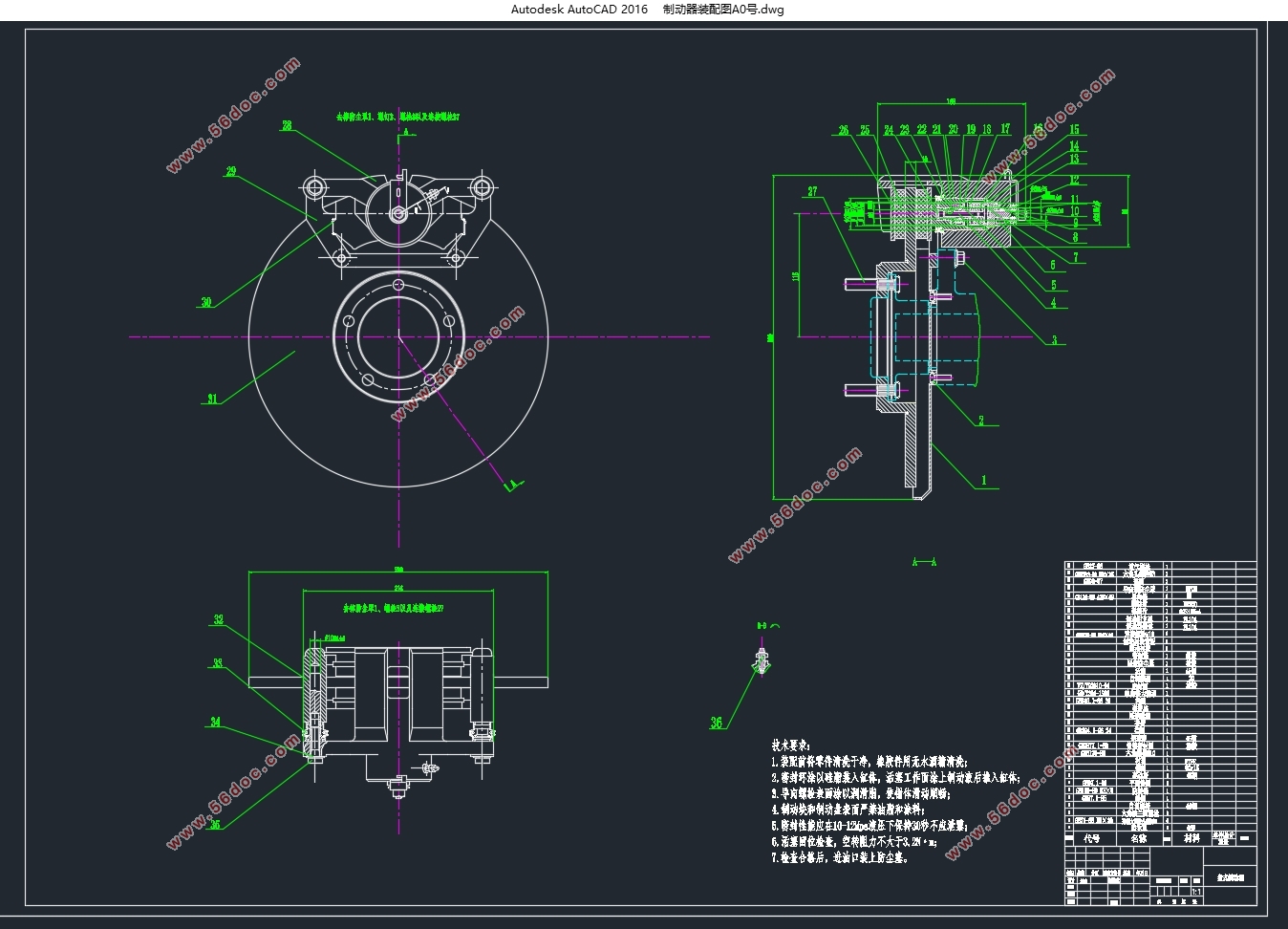
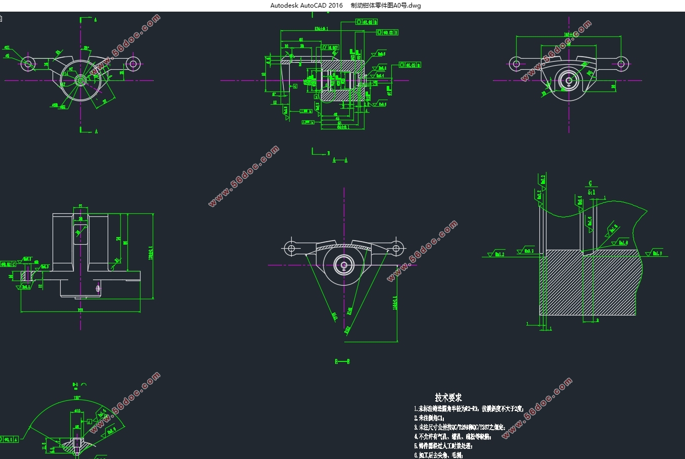
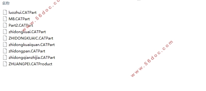
在这次本科毕业设计中,我们的目标是设计出微型车前轮制动器。本文中,先简单介绍了制动器的研究背景及意义,并对制动系统设计要求及评价标准进行了说明。然后简单比较了各种制动器的优缺点,并选择了浮钳盘式制动器作为本次设计中的微型车前轮制动器。下一步是分析计算本设计中制动系统的主要参数,包括制动力分配系数,同步附着系数等。接着选择盘式制动器的主要零部件,在设计计算之后进行了包括摩擦衬块磨损特性在内参数校核。最后依据设计和计算出的数据,分别用AUTO CAD和CATIA软件绘制出了该制动器的二维图和三维建模。
关键词: 制动盘; 浮钳盘式制动器; 制动驱动结构;
Abstract
As a very large automobile market in the world, China has a large number of cars, of which the number of mini-cars is particularly large. With the development of automotive technology, the speed of vehicles is also getting faster and faster, so the requirements for the safety of automobiles are very high. With such a large number of mini-vehicles, designing safer mini-vehicle brakes is particularly important.
In this undergraduate graduation project, our goal is to design a miniature front wheel brake. In this paper, the background and significance of the brake are briefly introduced, and the design requirements and evaluation criteria of the brake system are described. Then simply compare the advantages and disadvantages of various brakes, and choose the floating caliper disc brake as the front wheel brake of the mini vehicle in this design. The next step is to analyze and calculate the main parameters of the braking system in this design, including the braking force distribution coefficient and the synchronous adhesion coefficient. Then select the main components of the disc brake, after the design calculations, parameters including the wear characteristics of the friction pad check. Finally, according to the designed and calculated data, the two-dimensional map and three-dimensional modeling of the brake are drawn using AUTO CAD and CATIA software.
Key words: Brake disc Floating caliper brake Braking drive structure
制动器结构方案选择
2.1 整车结构参数
本次毕业设计为微型车前轮制动器的设计,参考车型为长安铃木奥拓,其整车结构参数如下所示。
外形尺寸:长/宽/高:3570/1600/1470mm;
整车质量:1200kg(满载),900kg(空载);
质心高度:0.55m(满载),0.58m(空载);
轴距:2360mm;
质心到前轴距离:1152mm(满载),968mm(空载).
质心到后轴距离:1208mm(满载),1392mm (空载);
轮胎规格:155/65 R14

目 录
第1章 绪论 1
1.1盘式制动器的研究背景及意义 1
1.1.1研究背景与发展历史 1
1.1.2.盘式制动器在国内外的研究现状 1
1.1.3盘式制动器的发展前景 2
1.2 制动器设计要求以及评价标准 2
1.2.1制动器的设计要求 2
1.2.2 制动器评价标准 3
第2章 制动器结构方案选择 5
2.1 整车结构参数 5
2.1.1 轮滚动半径 5
2.1.2 空、满载时的轴荷分配 5
2.2 制动器方案分析与选择 6
2.2.1 鼓式制动器 6
2.2.2 盘式制动器 7
2.3 制动器方案选择 9
第3章 制动系统的主要参数及选择 11
3.1 制动力分配系数 11
3.2 同步附着系数计算 13
3.3 制动器的制动强度以及附着系数利用率 15
3.4 制动器最大制动力矩 16
3.5.制动器因数 17
第4章 制动器主要零部件参数设计 18
4.1 制动盘参数选取设计 18
4.1.1 制动盘的直径D 18
4.1.2 制动盘的厚度h 18
4.2 制动器中制动钳的设计 18
4.3 摩擦衬块的主要参数设计 19
4.3.1 摩擦衬块平均半径 19
4.3.2 摩擦衬块有效半径 20
4.3.3 摩擦衬块的面积和磨损特性计算 21
4.3.4 摩擦衬块参数设计的校核 22
4.4 制动器的间隙调整 23
第5章 制动驱动机构的选择与计算 24
5.1 制动驱动机构的型式 24
5.2制动管路的选择 24
5.3液压制动驱动机构主要参数的计算 25
5.3.1制动轮缸的直径与工作容积计算 25
5.1.2制动主缸直径与工作容积 26
5.1.3制动踏板力与踏板行程 27
结论 29
参考文献 30
附录A 32
附录A1 电算说明书 32
1.程序简介与理论支持 32
2.程序源代码 32
3.程序运行结果 34
致谢 37
|
