东风K74M制动系统设计(含CAD零件图装配图,CATIA三维图)
来源:56doc.com 资料编号:5D25328 资料等级:★★★★★ %E8%B5%84%E6%96%99%E7%BC%96%E5%8F%B7%EF%BC%9A5D25328
资料以网页介绍的为准,下载后不会有水印.资料仅供学习参考之用. 密 保 惠 帮助
资料介绍
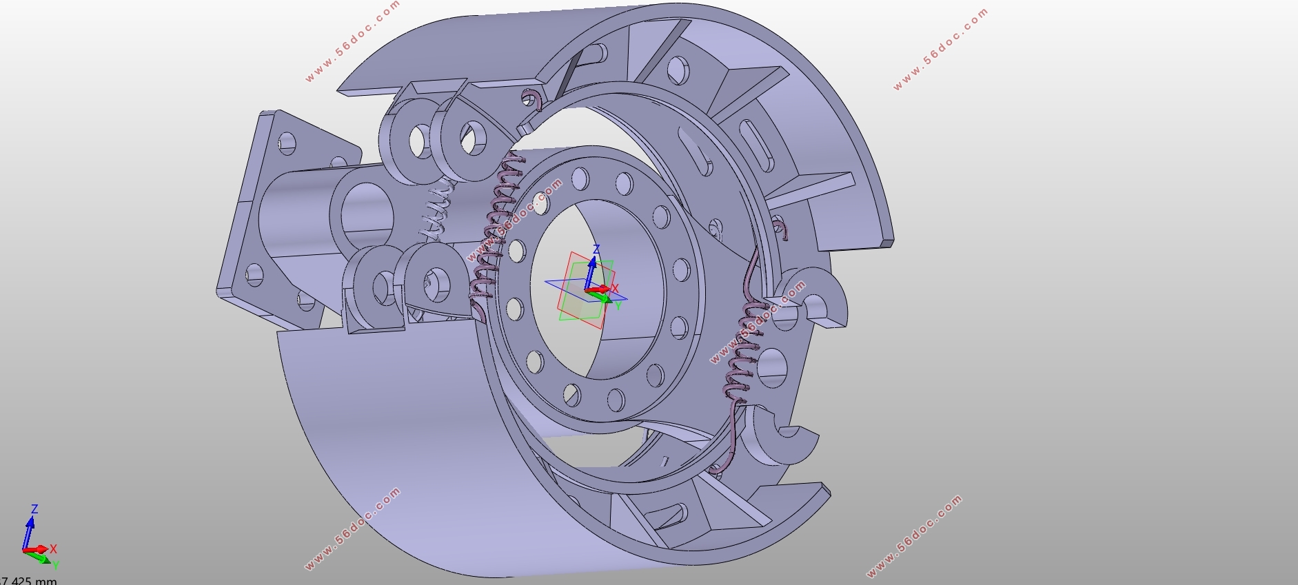
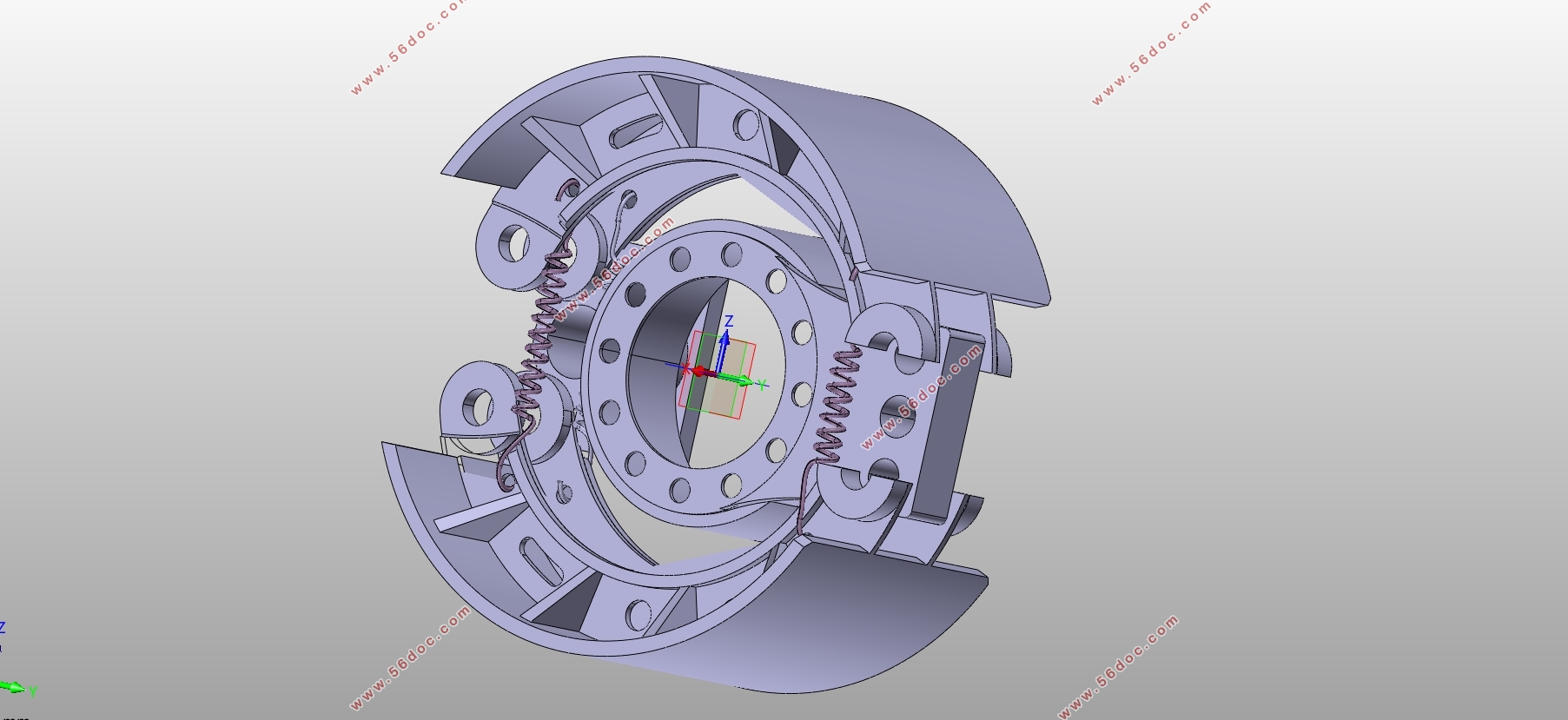
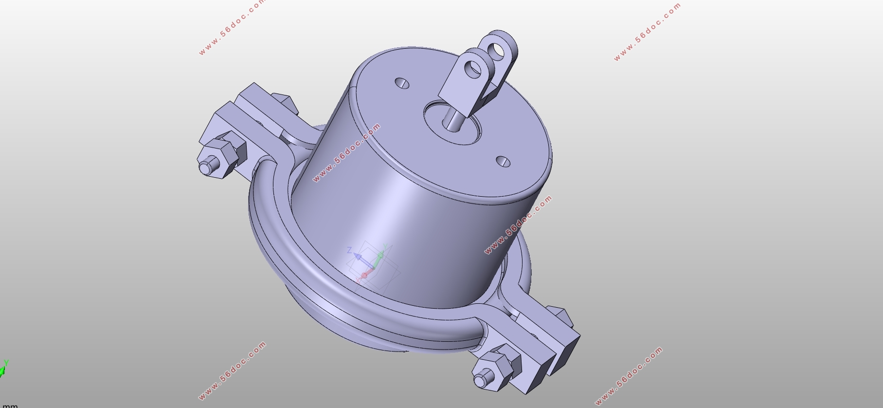
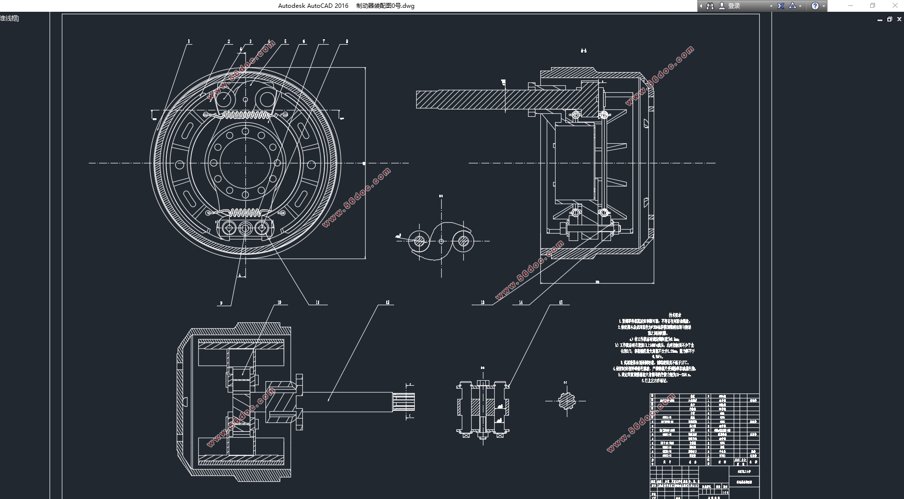
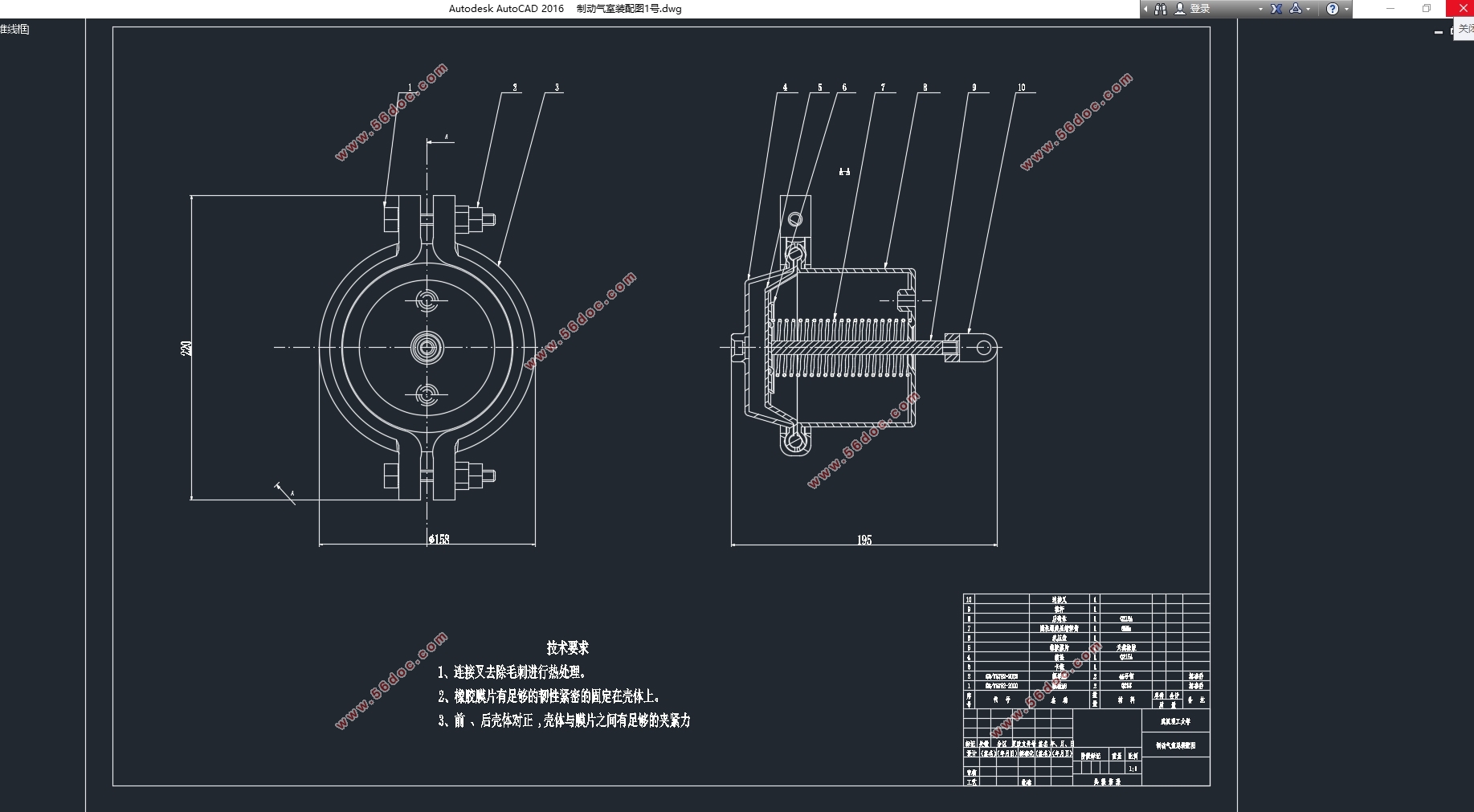
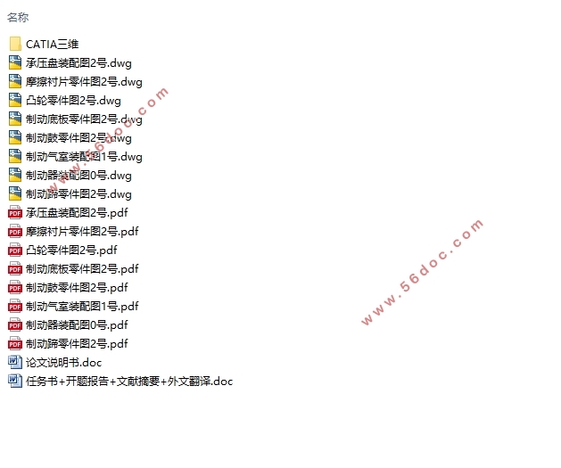
东风K74M制动系统设计(含CAD零件图装配图,CATIA三维图)(任务书,开题报告,文献摘要,外文翻译,论文说明书12000字,CAD图纸8张,CATIA三维图)
摘 要
本文主要是对与东风K74M相关车型的制动系统进行设计,如我们所知,汽车的制动系统的作用主要是在驾驶员下达制动指令后,以一定的适当的减速度减速直到汽车不再行驶,另外还有让汽车在下坡的时候可以保持一个不变的车速而不会发生车辆失控的现象,并能让汽车不发生意外的停在水平路面或者是坡道的上面。一辆汽车的制动性能是否符合要求将可以左右一个驾驶人的安全。尤其是对于长时间行驶且行驶环境更为复杂的商用车,制动系统的设计更是重中之重。
本论文主要是对于重型载货汽车东风K74M的制动系统进行选型设计,主要完成初始参数的选择,选型计算,性能校核等工作。目的是深入的学习重型的运输货物的汽车的制动系统的结构并完成一定的设计计算工作。
关键词:重型载货汽车;制动系统;鼓式制动器;制动力
Abstract
This article mainly designs the braking system related to the Dongfeng K74M. As we know, the function of the automobile's braking system is mainly to decelerate to a stop at a certain appropriate deceleration after the driver issues a braking command. There is also the fact that when the car is downhill, it can maintain a constant speed without losing control of the vehicle, and it can prevent the car from accidentally stopping on the level road or on the ramp. A car's braking performance can meet the requirements of a driver's safety. Therefore, relative to the design of the braking system is very important in the car design. Especially for commercial vehicles that travel for a long time and the driving environment is more complex, the design of the braking system is the most important thing.
This dissertation mainly selects the design of the braking system for heavy-duty truck Dongfeng K74M, and mainly completes the selection of initial parameters, calculation of type selection, and performance check. The purpose is to fully understand the structure of the heavy-duty truck brake system and complete certain design calculations.
Key Words: Heavy-duty truck; Braking system; Drum brake; Braking force
目 录
第1章 绪论 1
第2章 设计方案的比较和选择 2
2.1 设计目的及意义 2
2.2 设计背景简介 2
2.3 设计方案的比较和选择 3
第3章 制动系的主要参数及其选择 4
3.1制动力与其各轴之间的分配系数 4
3.2 制动器的结构参数与摩擦系数 7
3.2.1 制动鼓直径D 8
3.2.2制动蹄摩擦衬片的包角β和宽度b 8
3.2.3 制动器因数 8
3.2.4 其他制动器相关参数 10
第4章 制动器的设计计算 11
4.1 制动蹄上的制动力矩 11
4.2 摩擦衬片磨损特性计算 14
4.3 行车制动效能计算 16
4.4 驻车制动计算 17
第5章 制动器主要零件的结构设计 18
5.1 制动鼓 18
5.2 制动蹄 19
5.3 制动底板与支撑 19
5.4 凸轮张开机构 20
5.5 摩擦材料 20
5.6 制动器间隙的调整方法及相应的机构 20
第6章 气压制动驱动机构设计 22
6.1 制动气室计算 22
6.2 贮气罐 23
6.3 空气压缩机 24
6.4 制动阀与继动阀 25
第7章 结论 26
参考文献 27
致谢 28
|


