大学生方程式赛车的横向稳定杆设计(含CAD零件图装配图)(英文版)
来源:56doc.com 资料编号:5D25340 资料等级:★★★★★ %E8%B5%84%E6%96%99%E7%BC%96%E5%8F%B7%EF%BC%9A5D25340
资料以网页介绍的为准,下载后不会有水印.资料仅供学习参考之用. 密 保 惠 帮助
资料介绍
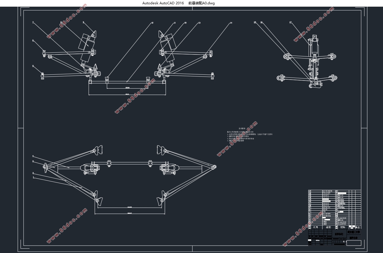
大学生方程式赛车的横向稳定杆设计(含CAD零件图装配图)(英文版)(任务书,开题报告,外文翻译,文献摘要,论文说明书英文版8000字,CAD图17张)
Abstract
The lateral stabilizer bar is the auxiliary component of the suspension system. It has the function of adjusting the roll angle when the vehicle is subjected to lateral acceleration. It can affect the stability of the whole vehicle and the operation of the driver. Based on the 2016 racing car of WUTE team of Wuhan University of Technology, the design of the transverse stabilizer bar of the 2017 car was carried out according to the experience of previous years, and the force analysis of the car was analyzed and checked. The application conditions and advantages and disadvantages of U shape and Z shape transverse stabilizing bars are put forward, and the design steps and train of thought of the lateral stabilizer bar are simplified. It provides some design guidelines for the design process of the formula suspension for the college students, and also provides some help and guidance for the design of the WUTE team racing car of Wuhan University of Technology in the future.
Key words: lateral stabilizer bar; suspension; roll stiffness; finite element analysis


Catalogue
Abstract 4
Chapter 1 Introduction 5
1.1The role of stabilizer bar 5
1.2 Structure and classification of lateral stabilizer bars 6
1.3 The working characteristics of the lateral stabilizer bar 6
1.4 Research status at home and abroad 7
1.5 The research content of this paper 8
Chapter 2 Modeling 9
2.1The comparison of several different suspension frames matches the horizontal stabilizer 9
2.2The modeling of u-shaped horizontal stabilizer 12
2.3The modeling of the rocker 12
2.4The modeling of connecting rod 13
Chapter 3 Calculation 16
3.1 Selection of vehicle side tilt gain / side slope stiffness 16
3.2 Stiffness calculation of lateral stabilizer bar 16
3.2.1. Deformation geometry relationship 17
3.2.2. Physical relationship 19
3.2.3. Static relationship 19
3.3 Calculation of load transfer 22
3.4 Force calculation of wheel side 23
3.5 Stiffness calculation provided by the shock absorber 24
Chapter 4 Analysis 26
4.1 Manual calculation check 26
4.1.1 Checking torsion strength of torsion bar 26
4.1.2 Check the strength of the vertical and rocker arms 26
4.1.3 Check the strength of the connecting rod 26
4.2 ANSYS software analysis and verification 27
4.2.1 Check torsion strength of torsion bar 27
4.2.2 Check the strength of the vertical bar 27
4.2.3 Check the strength of the connecting rod 30
4.2.4 Check the strength of the rocker arm 30
4.3 Analysis of fatigue strength 35
Chapter 5 Conclusion 37
Reference 38
Acknowledge 39
|


