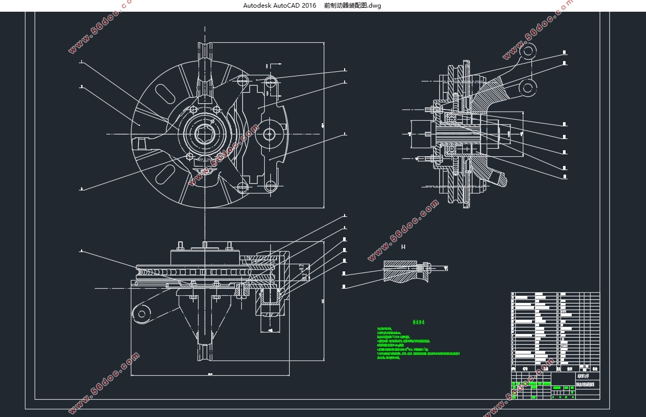
捷达轿车制动系统的设计(含CAD零件图装配图)(任务书,开题报告,文献摘要,外文翻译,论文说明书16000字,CAD图7张)
摘要
随着汽车的保有量和生产量逐年提升,汽车已经成为人类社会不可缺少的交通工具。但同时,由汽车引发的交通问题也成为了全球性的社会问题。作为保障汽车安全性的系统之一,制动系统的设计因此显得尤为重要。
本论文将以轿车的制动系统作为研究对象。首先对制动器的两种主要形式盘式制动器和鼓式制动器的分类及其工作原理进行详细介绍。并对制动驱动机构的形式进行讨论分析。由于本次制动系统的设计是以捷达轿车作为参考对象,故最终选取前后均为盘式制动器,并采用全液压驱动机构的形式。对前后盘式制动器的参数设计。首先利用收集整理的参数,对轿车的同步附着系数、前后制动力分配参数、制动力矩等参数进行计算。然后开始对盘式制动器的结构、材料、具体参数进行设计计算。最后对制动驱动机构中的制动主缸、制动轮缸、踏板力和踏板行程进行计算。
完成了制动器和驱动机构的部分参数设计后,然后对其进行校核。对制动系统制动性能的评价,计算了制动加速度、制动距离等参数;对摩擦片的磨损特性、对制动器的热容量和温升进行校核。同时,利用Matlab编程绘制制动力分配曲线图。利用Catia对制动器的制动盘、轮毂、卡钳、支架、制动块等零件进行建模,然后装配,最后在用CAD完成装配图和部分零件图的绘制。
关键词:捷达轿车;盘式制动器;建模;CAD
Abstract
With the increase in car ownership and production increased year by year, the car has become an indispensable means of transport in human society. But at the same time, traffic problems caused by cars have become a global social problem. As one of the systems to ensure vehicle safety, the design of the braking system is therefore of particular importance.
This paper will take the car's braking system as the research object. Firstly, the classification and working principle of two kinds of disc brakes and drum brakes of brake are introduced in detail. Then the form of the brake drive mechanism is discussed and analyzed. As the design of the braking system is based on Jetta sedan as a reference object, so the final selection before and after the disc brakes, and the use of full hydraulic drive mechanism in the form.Firstly, the parameters such as the synchronizing adhesion coefficient, the front and rear braking force distribution parameters and the braking torque are calculated by using the parameters of collecting and sorting. And then began to disc brake structure, materials, specific parameters of the design calculation. Finally, the braking cylinder in the brake drive mechanism, brake wheel cylinder, pedal force and pedal stroke are calculated.
After the completion of the brake and drive part of the design parameters, and then check it. The braking performance of the braking system is evaluated, and the parameters such as braking acceleration and braking distance are calculated. The wear characteristics of the friction plate are checked and the heat capacity and temperature rise of the brake are checked. At the same time, using Matlab programming to draw the braking force distribution curve.Use Catia to model brake discs, wheels, calipers, brackets, brake blocks and other parts, and then assembled, and finally in CAD with assembly drawings and parts of the drawing.
Key words:Jetta sedan;disc brake;Modeling;CAD
制动系统主要参数的选取和计算
制动系统设计流程一般为:明确设计目标,收集整理相应的参数;然后根据相应的国家标准和公式计算出所需的参数;然后参考同类型轿车并根据公式计算出制动器的结构尺寸;进行校核确定数据的合理性;最终确定尺寸达到设计目标。
此次设计的对象是捷达轿车制动系统,通过查阅相关维修手册以及网络上的基本数据可以得到如下参数:
表3.1捷达轿车部分参数
参数 数值
整备质量 1100kg
满载质量 1500kg
质心到前轴的距离a 1287mm
质心到前轴的距离b 1188mm
前轴负荷 780kg
后轴负荷 720kg
质心高度空载 0.58m
质心高度满载 0.55m
而市场上常见的捷达轿车的轮胎尺寸为: 185/60R14 85H,即:
表3.2捷达轿车轮胎部分参数
轮胎胎面宽 185mm
扁平率(高宽比) 60
轮辋外径 15in≈381mm


目录
第1章 绪论 1
1.1 制动系统设计的意义 1
1.2 制动系统研究现状 1
1.3 本次制动系统设计任务 1
第2章制动系统方案论证分析与选择 3
2.1 制动系统简介 3
2.2 制动器形式方案分析 3
2.2.1 鼓式制动器 3
2.2.2 盘式制动器 7
2.2 制动驱动机构的机构形式选择 9
2.2.1 人力驱动机构 9
2.2.2 动力驱动机构 9
2.2.3 伺服制动 10
2.3液压分路系统的形式与选择 10
2.4本章小结 11
第3章制动器的设计计算 12
3.1 制动系统主要参数的选取和计算 12
3.1.1 同步附着系数 12
3.1.2 前后制动力矩分配系数 13
3.1.3 制动器制动力矩的确定 14
3.2 前轮盘式制动器的设计 15
3.2.1 制动盘设计 15
3.2.2 制动钳总成设计 15
3.2.3 盘式制动器制动力的计算 17
3.3本章小结 18
第4章液压驱动机构的设计 19
4.1 制动轮缸直径的确定 19
4.2 制动主缸直径的确定 19
4.3 制动踏板力和制动踏板行程 20
4.4 本章小结 21
第5章制动性能分析 22
5.1 制动性能评价指标 22
5.1.1 制动效能 22
5.1.2 制动效能的恒定性 23
5.1.3 制动时汽车的方向稳定性 23
5.2 制动器制动力分配曲线分析 23
5.3摩擦衬块的磨损特性计算 24
5.3.1 比能量耗散率 24
5.3.2 比摩擦力 25
5.4 制动器的热容量和温升校核 26
5.5 驻车制动计算 27
5.6 本章小结 28
第6章总结与展望 29
参考文献 30
附录A制动器主要部件三维建模 31
附录B Matlab程序绘制制动力分配曲线图 34
致谢 35
|


