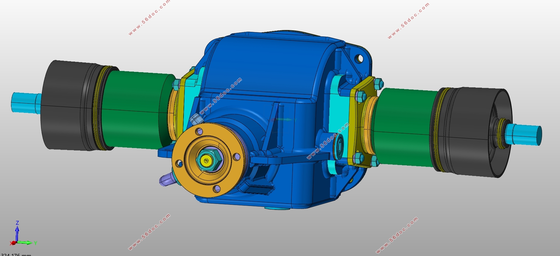
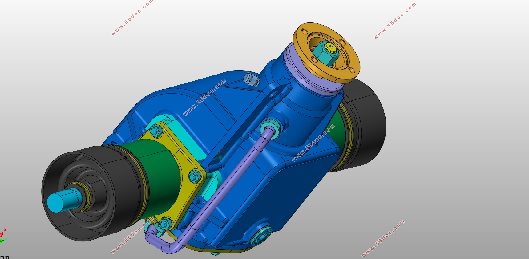
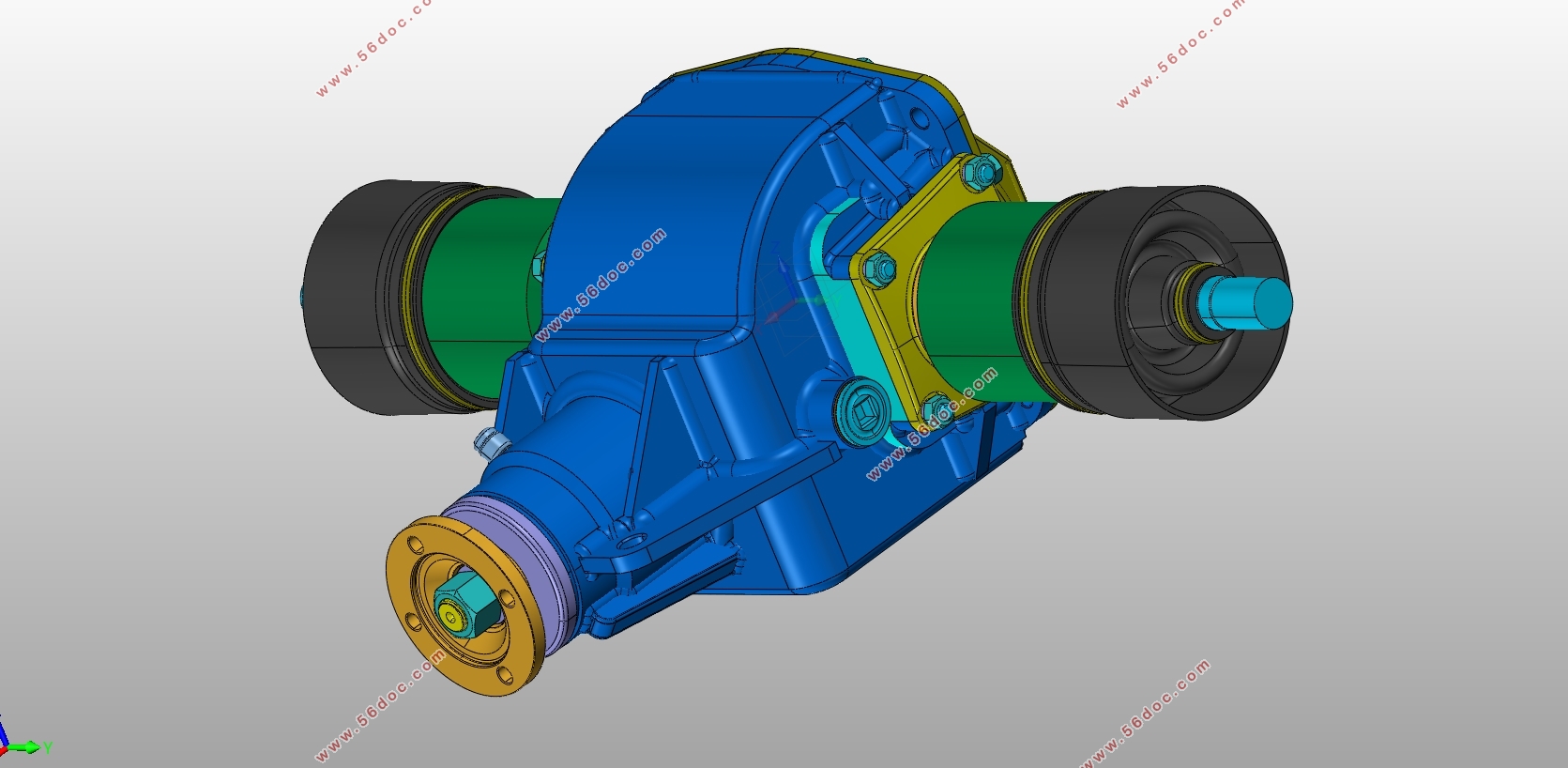
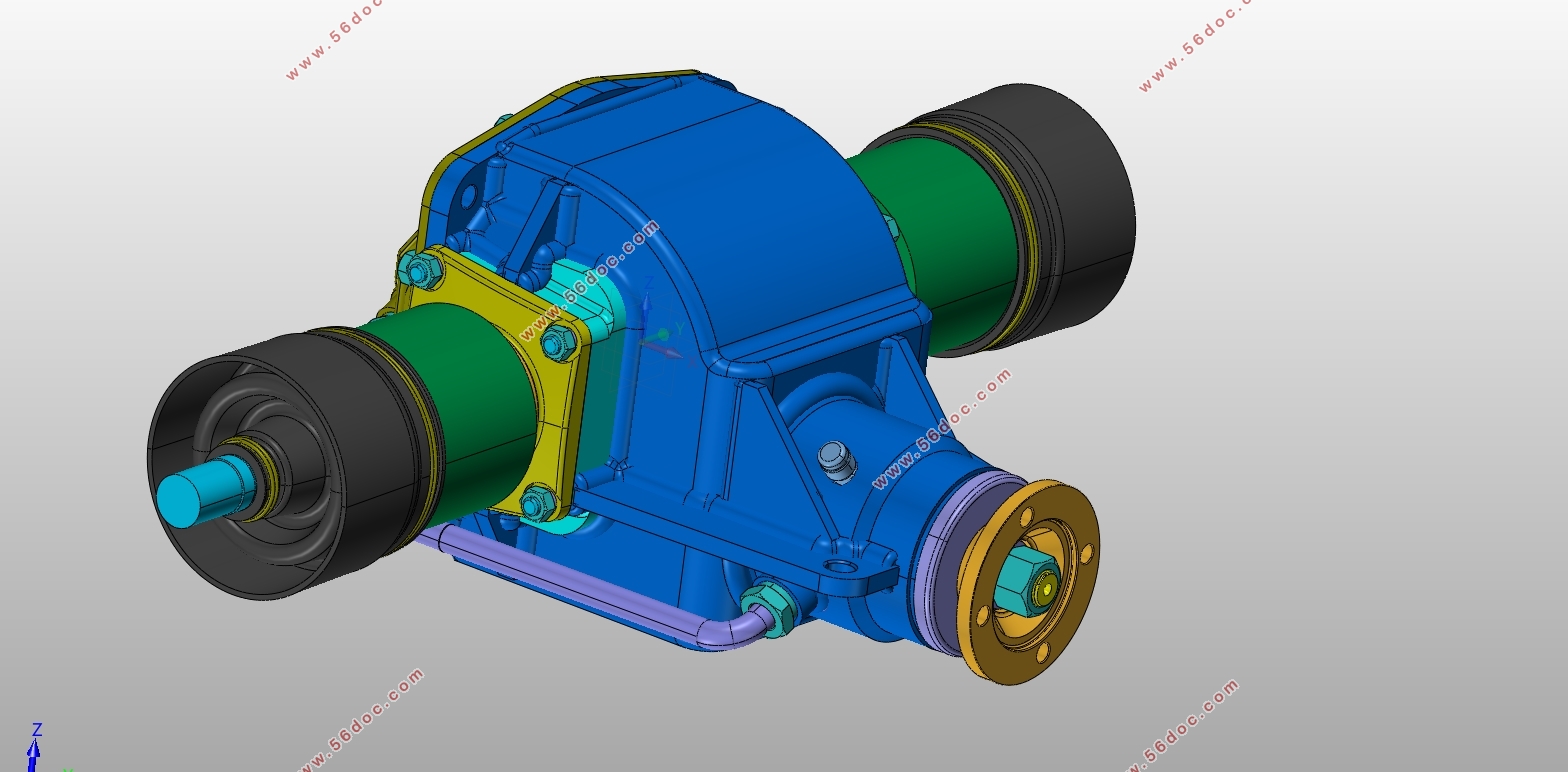
1.6升轿车驱动桥设计Drive axle design for 1.6 liter sedan(英文)(含CAD零件图装配图,CATIA三维图)(任务书英文,开题报告英文,文献摘要英文,论文说明书英文版12000字,CAD图6张,CATIA三维图)
Drive axle design for 1.6 liter sedan
Abstract
With the development of the automobile industry and the continuous improvement of productivity, the dynamic performance of the car attracts more and more attention from people, while the good dynamic performance does not only result the performance of the engine, but also the entire power system, where drive axle plays a very important role.Located at the end of transmission, drive axle can change the transmission speed and torque, and delivers them to the drive wheel mechanism. Composed offinal drive, differential, wheel drive, drive axle housing,semi axle and constant velocity universal joint, its components also play a vital part in vehicle. Like the drive bridge acts on the transport of vertical force, longitudinal force and lateral force, as well as braking torque and reaction force between the road surface and the frame or the body. Therefore, the design of drive axle plays an important part in vehicle design.
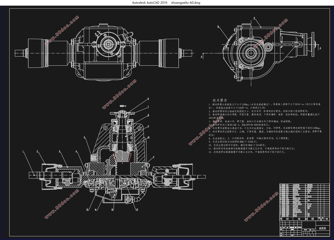
This design refers to the design of the traditional drive axle, and carries on the the 1.6 liter traditional sedan car. As all through the relevant parameters are given, we should determine the structure design of the drive axle like the single-stage final drive, symmetrical bevel gear differential, full floating semi axle structure; then calculate the final drive, differential, semi axle and other parts of the main parameters and determine its the sizewithin structures, and do strength check, in order to meet the design requirements. To finish 3D geometry model of all parts we are using the three-dimensional modeling software CATIA and CAD, to draw the differential straight bevel gear and hypoid gear reducer using parametric modeling.
Key Words:Drive axle; Final drive; Differential; CATIA; CAD

Contents
Abstract 4
Chapter 1 Introduction 8
1.1 Overview 8
1.2 The research status of the design and analysis of drive axle 10
1.3 The following basic requirements when designing a drive axle 10
Chapter 2 Drive axle structure scheme 11
2.1 Design requirements of drive axle 11
2.2 Open type drive axle 12
2.3 Divided drive axle 13
2.4 Selection of drive axle assembly structure 14
2.5 Input parameters 15
Chapter 3 Final drive design 16
3.1 The structure of the final drive 16
3.1.1 The deceleration form of final drive 17
3.1.2 Type of gear for final drive 19
3.2 Selection and design calculation of basic parameters for final drive 21
3.2.1 Determination of the final reduction ratio 21
3.2.2 Determination of calculation load of final drive 22
3.2.3 Selection of main parameters of bevel gear for final drive 24
3.2.4 Geometric dimension calculation of hypoid gear for final drive 29
3.2.5 Strength calculation of hypoid bevel gear for final drive 30
3.4 Material and heat treatment of the gear of the final drive 37
3.5 Lubrication of final drive 39
Chapter 4Differential design 40
4.1 Differential overview 40
4.2 The selection of the type of mechanism of the differential 41
4.3 The principle of symmetrical bevel planetary gear differential mechanism 41
4.4 Structure of symmetrical bevel planetary gear differential 43
4.5 Design of symmetrical bevel planetary gear differential 43
4.5.1 Selection of the basic parameters of the differential gear 44
4.5.2 Calculation of geometrical dimension of differential gear 46
4.5.3 Strength calculation of bevel gear for differential 47
4.6 The material of the differential gear 48
Chapter 5 Semi axle design 49
5.1 Brief introduction of semi axle 49
5.2 Selection of semi axle 49
5.3 Dimension design and check of semi axle 50
5.3.1 Load calculation of semi axle 50
5.3.2 The shaft diameter 51
5.3.3 Strength check of semi axle 51
5.4 Materials and heat treatment of semi shafts 52
Chapter 6 Drive axle housing 53
6.1 Selection of drive axle housing 53
6.2 Calculation of static bending stress of bridge shell 53
6.3 Strength calculation of bridge shell under impact loading of rough pavement 54
6.4 Calculation of axle housing strength of automobile under maximum traction 55
6.5 Strength calculation of axle housing for automobile emergency braking 56
Reference 58
Acknowledgment 59 |


