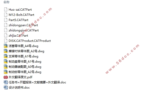
中型轿车前轮制动器设计(含CAD零件图装配图,CATIA三维图)(任务书,开题报告,文献摘要,外文翻译,论文说明书10000字,CAD图纸6张,CATIA三维图)
摘 要
近年来,汽车保有量不断增长,汽车的安全问题成为了现代汽车研究方向的重要课题。其中整车的制动系统部分是保障汽车安全性的一个重要环节,从而汽车的制动系统设计对整车设计而言显得尤为重要。本文以2017款帕萨特380TSI DSG御尊版中型轿车为例,针对中型轿车制动时方向稳定性差、制动距离长等问题,对该车型的前轮制动器零部件(制动盘、制动钳、制动块等)参数进行设计计算,并对其零部件进行优化设计,从而来提高汽车的制动性能。
关键词:制动系统设计;前轮制动器;零部件参数;优化设计
Abstract
In recent years, the number of car ownership has continued to increase, and the safety of automobiles has become an important issue in the direction of modern automotive research.Among them, the braking system of the vehicle is an important part of ensuring the safety of the vehicle. Therefore, the design of the braking system of the vehicle is particularly important for the design of the vehicle. This article takes the 2017 Passat 380TSI DSG Yuzun mid-size sedan as an example, focusing on the problem of poor steering stability and long braking distance of medium-sized passenger cars, and the front-wheel brake components (brake discs, brake calipers, The brake pads and other parameters are designed and calculated, and their components are optimized for design so as to improve the braking performance of the front wheel brake and ensure the safety of the vehicle.
Keywords: brake system design; front-wheel brakes; component parameters; optimization design
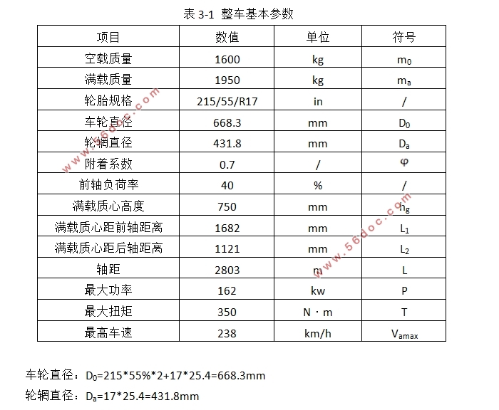
整车基本参数
项目 数值 单位 符号
空载质量 1600 kg m0
满载质量 1950 kg ma
轮胎规格 215/55/R17 in /
车轮直径 668.3 mm D0
轮辋直径 431.8 mm Da
附着系数 0.7 /
前轴负荷率 40 % /
满载质心高度 750 mm hg
满载质心距前轴距离 1682 mm L1
满载质心距后轴距离 1121 mm L2
轴距 2803 m L
最大功率 162 kw P
最大扭矩 350 N•m T
最高车速 238 km/h Vamax
车轮直径:D0=215*55%*2+17*25.4=668.3mm
轮辋直径:Da=17*25.4=431.8mm
目 录
1 绪论 1
1.1设计目的(制动系统) 1
1.2国内外研究现状(制动系统) 1
1.3 制动系统简介 2
1.4 制动系统的类型 3
1.4.1 以制动系统的制动能源分类 3
1.4.2 以制动能量的传输方式分类 3
1.4.3 以制动系统的作用分类 3
1.5 制动系统的设计要求 3
2 制动器的类型及选择 4
2.1 盘式制动器 4
3 制动系的主要相关系数的设计计算 5
3.1 制动力及其分配系数的设计计算 5
3.2 其他基本参数的设计计算 7
3.3 制动器的最大制动力矩的计算 7
3.4 制动器因数的选择 8
3.5应急制动和驻车制动所需的制动力矩 8
3.5.1 应急制动的制动力矩 8
3.5.2 驻车制动的制动力矩 9
4 盘式制动器的参数设计 10
4.1 盘式制动器的基本构造及工作原理 10
4.2 盘式制动器的基本参数设计 10
4.2.1直径D(制动盘) 10
4.2.2厚度h(制动盘) 11
4.2.3内半径R1和外半径R2(摩擦衬块) 11
4.2.4工作面积A的确定(摩擦衬块) 11
4.3制动力矩的设计计算(盘式制动器) 12
4.5 摩擦衬块的磨损特性的校核 13
5 制动缸的选择 16
5.1 液压伺服制动系的类型及选择 16
5.2分路系统(制动管路) 16
5.3优缺点(液压制动) 16
5.3.1优点(液压制动): 16
5.3.2缺点(液压制动): 16
5.4设计计算(液压制动驱动机构) 16
5.4.1直径dW的选择和工作容积的计算(制动轮缸) 16
5.4.2 制动主缸的选择 17
5.4.3直径和工作容积的计算(制动主缸) 17
5.4.4 制动踏板力的计算 18
5.4.5行程的计算(制动踏板) 18
6 制动器主要零部件设计 20
6.1 制动盘 20
6.2 制动钳 20
6.3制动块 20
6.4摩擦衬块的材料选取 20
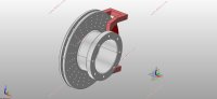
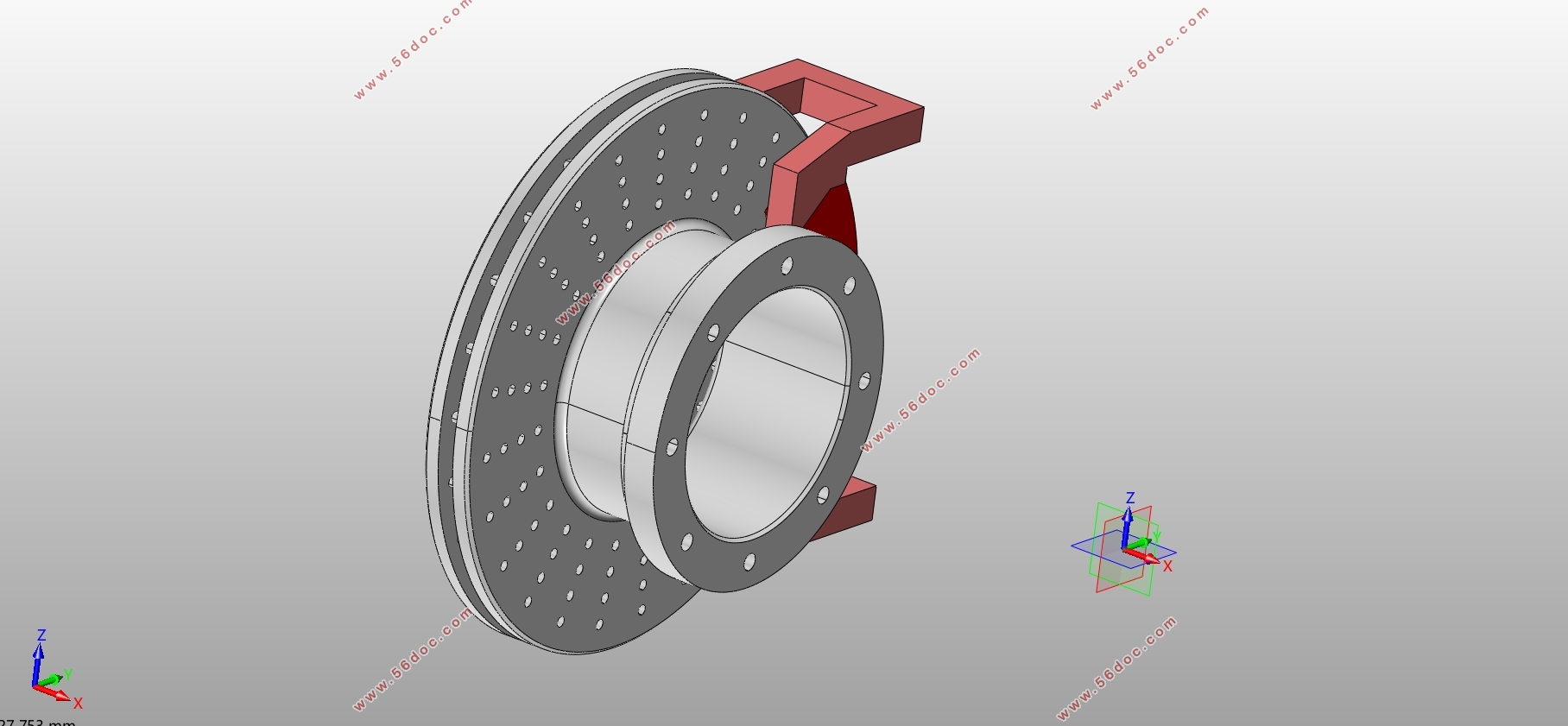
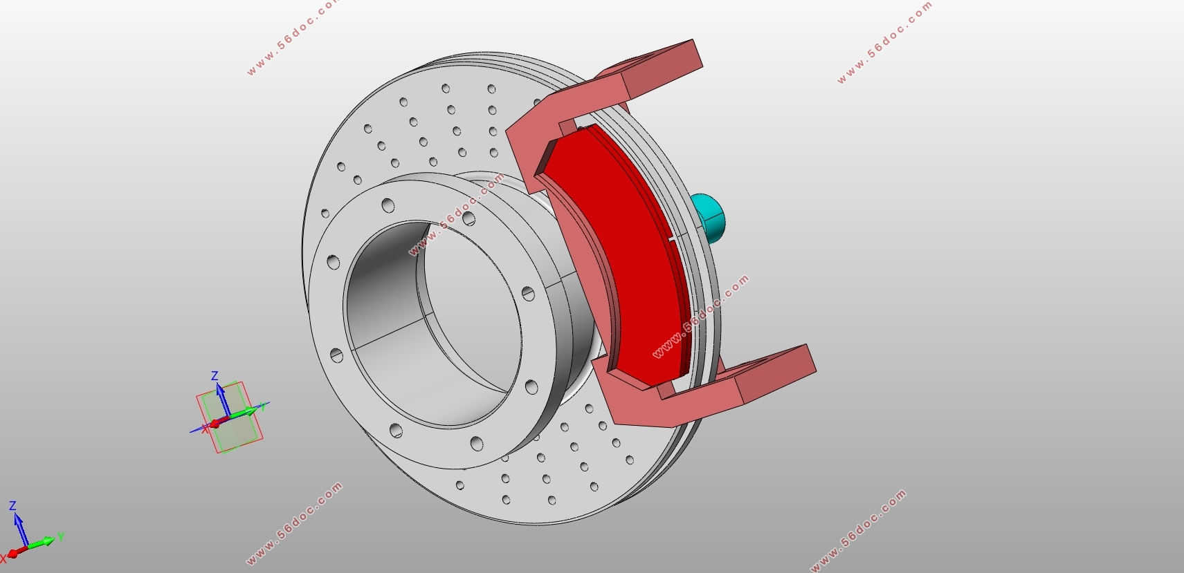
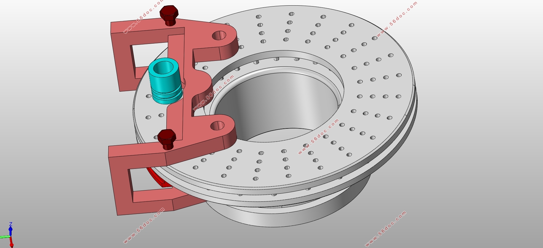
7 制动器零部件三维设计 22
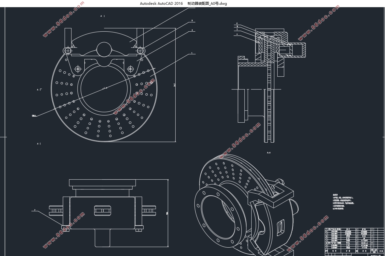
7.1 制动器装配图 22
7.2 制动盘 23
7.3 支架 23
7.4 制动钳体 24
7.5 活塞 24
参考文献 25
附录A MATLAB编制制动力分配曲线 27
致谢 28
|