200挤出机液压缸系统设计(含CAD图)(任务书,文献综述,设计说明书12800字,CAD图纸3张)
摘 要
液压缸是实现液压能转变成机械能的装置,它是用来做摆动运动(或直线往复运动)的执行元件,拥有比较简单的结构并且工作可靠,完成摆动运动时,无传动间隙且可以避免减速装置的影响,使其平稳运动,现今在各机械的液压领域,都得到了广泛的实践应用。
液力与液压传动的工作介质都是液体,用此方式来进行能量的传递,液力传动是将机械能转变成液体动能,再将液体动能转变为机械能的装置,可以把能量进行传递,也是液体传递的一种分支,它的组成主要是几个叶轮的非刚性连接。而液压传动不同,它的传递方式是通过工作介质来进行控制与传递能量,它们均为流体传动,目前在各个领域已得到广泛认可和采用。
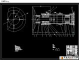
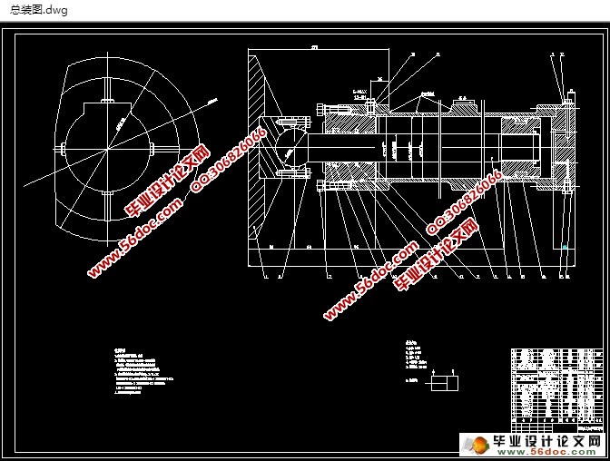
本次设计主要是对液压缸系统的设计方法来进行系统的研究,通过对液压缸建立CAD原型得出了以下研究成果:1.在分析液压缸的基本工作原理上,总结它的主要安装以及工作形式。2.做出其装配图,通过了解装配图的特征,来建立模型。3.结合液压缸的装配CAD系统模型,来开发其系统CAD软件原型系统。4.通过计算的方法来选择需要的液压元件。5.最终对所设计的系统进行检验。6.绘制最终正式的系统图与文件。
关键词:液压缸;液压传动;液力传动
Abstract
Hydraulic cylinder is a simple and reliable device that performs linear reciprocating motions and converts hydraulic energy to mechanical energy. When hydraulic cylinder works, Reduction gear can be avoided, and there is no rotational clearance. Due to its reliable property, Hydraulic cylinder are widely applied in the mechanical hydraulic system. Hydraulic cylinder output force is proportional to the effective area of piston and the pressure difference. Hydraulic cylinder is primarily composed of cylinder, cylinder head, piston, piston rod, sealing device, buffer device, and exhaust. buffer device and exhaust are applied on a case by case basis, while other equipment are usually necessary.
Hydraulic transmission and hydraulic transmission both employ working liquids for energy conversion. Hydraulic transmission is in fact a branch of liquid drive, and consists of a non rigid connection drive device made up of several impellors. This device converts mechanical energy to the kinetic energy of the working liquid, and then converts to mechanical energy again for energy transportation; hydraulic transmission employs working liquid to convert energy and perform control. Hydraulic transmission and pneumatic drive are named fluid drive,which is a new technology based on hydrostatic pressure transmission principle introduced by Pascal in the 1600. Therefore, they have been widely used a wide array of fields.
This work performs systematic research into the hydraulic cylinder parametric design method to establish hydraulic cylinder CAD prototype software system. The major results are: 1. Analyzed the working conditions of hydraulic system, and generalized the working and installing methods of hydraulic cylinder based on the analysis results; 2. Drafted the schematic of the hydraulic system, and developed a feature-based product model for hydraulic cylinder。We studied the modeling methods for the database of standard parts suitable for parametric designs of hydraulic cylinder, and developed a database model for the hydraulic cylinder; 3. Constructed a parametric CAD model and a prototype system for hydraulic cylinder; 4. Calculated hydraulic system and selected hydraulic element; 5. Validated the hydraulic system; 6. Draw official graphs and compiled technology files.
Key words:Hydraulic cylinder; hydraulic transmission; hydraulic transmission

目 录
引言 1
第一章液压传动的概述 2
1.1 简介 2
1.2 应用领域 2
1.3 传动原理 2
1.4 主要组成 3
1.4.1 动力元件(油泵) 3
1.4.2 执行元件(油缸、液压马达) 3
1.4.3 控制元件 3
1.4.4 辅助元件 3
1.4.5 工作介质 3
1.5 表达符号 4
1.6 现状及其展望 4
第二章液压缸的结构 6
2.1 液压缸连接方式 6
2.1.1 法兰型液压缸 6
2.1.1 螺纹盖型液压缸 6
2.1.3 拉杆型液压缸 6
2.1.4 液压缸安装方式 7
2.2 特殊液压缸 9
2.2.1 特殊工质液压缸 9
2.2.2 多级液压缸 9
2.2.3 组合液压缸 10
2.2.4 电液伺服液压缸 10
2.2.5 特殊结构液压缸 11
第三章液压缸的主要参数计算 13
3.1 液压缸种类 13
3.2 计算主要参数 13
3.2.1 液压缸公称压力 13
3.2.2 液压缸尺寸与面积比 13
3.2.3 活塞的理论推拉力 15
3.2.4 液压缸效率 t 17
3.2.5 液压缸负载率 18
3.2.6 活塞瞬间线速度 18
3.2.7 活塞的作用力F 20
3.2.8 活塞加速度a 21
3.2.9 活塞加(减)速时间ta(td) 21
3.2.10 活塞加(减)速行程Sa(Sd) 22
3.2.11 液压缸流量 22
3.2.12 液压缸功率P 23
第四章液压缸主要零部件设计 24
4.1 缸筒的设计计算 24
4.1.1 主要技术要求 24
4.1.2 缸筒结构 24
4.1.3 缸筒计算 26
4.1.4 缸筒厚度计算 28
4.1.5 缸筒厚度验算 29
4.1.6 缸筒底部厚度计算 29
4.1.7 缸筒焊接连接计算 29
4.1.8 缸筒材料 31
4.1.9 缸筒内壁表面加工公差和粗糙度ISO4394 31
4.2 导向环的设计计算 32
4.2.1 导向环主要优点 32
4.2.2 导向环的型式 32
4.2.3 导向环的尺寸不同 34
4.3 活塞杆导向套 34
4.4 中隔圈的设计计算(限位圈) 35
4.5 辅件 36
结论 42
参考文献 43
致谢 44
|