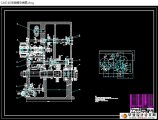
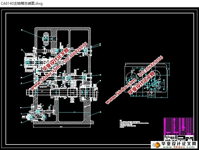
CA6140机床主轴箱结构设计(含CAD零件装配图)
来源:56doc.com 资料编号:5D14404 资料等级:★★★★★ %E8%B5%84%E6%96%99%E7%BC%96%E5%8F%B7%EF%BC%9A5D14404
资料以网页介绍的为准,下载后不会有水印.资料仅供学习参考之用. 密 保 惠 帮助
资料介绍
CA6140机床主轴箱结构设计(含CAD零件装配图)(任务书,文献综述,论文说明书12000字,CAD图纸3张)
摘 要
车床是众多车床中应用最广泛的一种,约占车床类总数的65%,因其主轴以水平方式放置故称为卧式车床。普通车床的主轴箱又称床头箱,它的主要任务是将主电机传来的旋转运动经过一系列的变速机构使主轴得到所需的正反两种转向的不同转速,同时主轴箱分出部分动力将运动传给进给箱。主轴箱中等主轴是车床的关键零件。
本文对机床床头箱进行了设计,主轴箱是机床的动力源将动力和运动传递给机床主轴的基本环节,其机构复杂而巧妙,要实现其全部功能在软件中的模拟仿真工作量非常大。这次设计的效果没有预计的完美,有一些硬件方面的原因,在模拟仿真的时候,由于计算机的配置不能达到所需要求,致使运行速度非常慢,不但时间上拖了下来,而且所模拟的效果很不理想。我接受的设计任务是对车床的主轴箱进行设计。主轴箱的结构繁多,考虑到实际硬件设备的承受能力,在进行三维造型的时候在不影响模拟仿真的情况下,省去了很多细部结构。
关键词: 轴; 齿轮; 主轴; 变速
Abstract
Common lathe is one of the the most widely used, accounting for 65% of the total number of lathes , because of the spindle horizontally placed so called horizontal lathe.Mainspindle: also known as the headstock, its main task is coming from the main motor rotation speed through a series of institutions required for the spindle to be turned to different positive and negative speed, while spindle box allocate part of the power the campaign to pass into the box. Lathe headstock spindle is the key to the middle part.
CA6140-type feed box: also known as the cutting box, feed tank equipped with a variable speed feed motion in the body, it can adjust the speed to change mechanism, obtain the required feed rate or screw pitch, the light bar or screw through the spread of sports knife frame for cutting.Screw and light bars: to connect the feed box and the crates and deliver the motion and driving force to slide crate ,to make crate to get the vertical linear slide motion.
Keywords: Haft; Gear; Spindle box; Variable speed
目 录
引言 1
第一章 传动方案和传动系统图的拟定 2
第二章 主要设计零件的计算和验算 4
2.1 主轴箱的箱体 4
2.2 传动系统的I轴及轴上零件设计 5
2.2.1 普通V带传动的计算 5
2.2.2 多片式摩擦离合器的计算 7
2.2.3 齿轮的验算 8
2.2.4 传动轴的验算 10
2.2.5 轴承疲劳强度校核 11
第三章 传动系统的Ⅱ轴及轴上零件设计 12
3.1 齿轮的验算 13
3.2 传动轴的验算 15
3.3 轴组件的刚度验算 17
第四章 传动系统的Ⅲ轴及轴上零件设计 19
4.1 齿轮的验算 19
4.2 传动轴的验算 21
4.3 轴组件的刚度验算 22
第五章 传动系统的Ⅳ轴及轴上零件设计 24
5.1 齿轮的验算 25
5.2 传动轴的验算 27
5.3 轴组件的刚度验算 28
第六章 传动系统的Ⅴ轴及轴上零件设计 30
6.1 齿轮的验算 30
6.2 轴组件的刚度验算 32
结论 34
参考文献 35
致谢 36
|