数控机床上下料机械手设计(含CAD零件装配图)
来源:56doc.com 资料编号:5D17576 资料等级:★★★★★ %E8%B5%84%E6%96%99%E7%BC%96%E5%8F%B7%EF%BC%9A5D17576
资料以网页介绍的为准,下载后不会有水印.资料仅供学习参考之用. 密 保 惠 帮助
资料介绍
数控机床上下料机械手设计(含CAD零件装配图)(任务书,论文说明书10000字,CAD图纸4张)
摘要
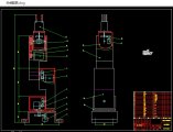
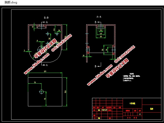
通过大学本科四年对机械设计制造及其自动化专业的所学知识进行整理,对工业机器人各部分机械结构设计和功能的论述和分析,设计了一种的用于机床上下料的机械手。本设计的主要内容是5R关节型机械手的结构设计,上下料机械手的主要任务是在各个加工工序的数控机床和自动生产线上运送工件,能实现生产工序上下料自动化。针对各个关节处采用独立的电机驱动。各个操作臂由五个转动副串联而成,操作臂包括基座、腰部、手臂、腕部、手爪。并对各关节的伺服电机的选择和传动进行了设计计算,对进行主要零件校核计算。
关键词: 关节型; 机械手; 多自由度
Abstract
Through four years of undergraduate mechanical engineering and automation professional to organize the knowledge of the various parts of industrial robots and mechanical design features discussion and analysis, design a robot one machine for loading and unloading. The main contents of this design is the design 5R articulated robot, the main task of loading and unloading robot CNC machine tools in various manufacturing processes and automatic production line delivery of the workpiece, to achieve the production process automation and unloading. For each of the joints with a separate motor. Each operating arm by the rotation of five deputy in series, including the base operating arm, waist, arm, wrist, gripper. And each joint servo motor and drive selection carried out design calculations, performed the main parts of the checking calculation.
Key words: Joint type; Manipulator; Many degrees of freedom

目 录
第一章引言 1
1.1 选题背景 1
1.2 机械手的发展动态 2
1.3 机械手的分类 3
1.4 课题研究的意义 4
第二章机械手结构原理和工作要求分析 5
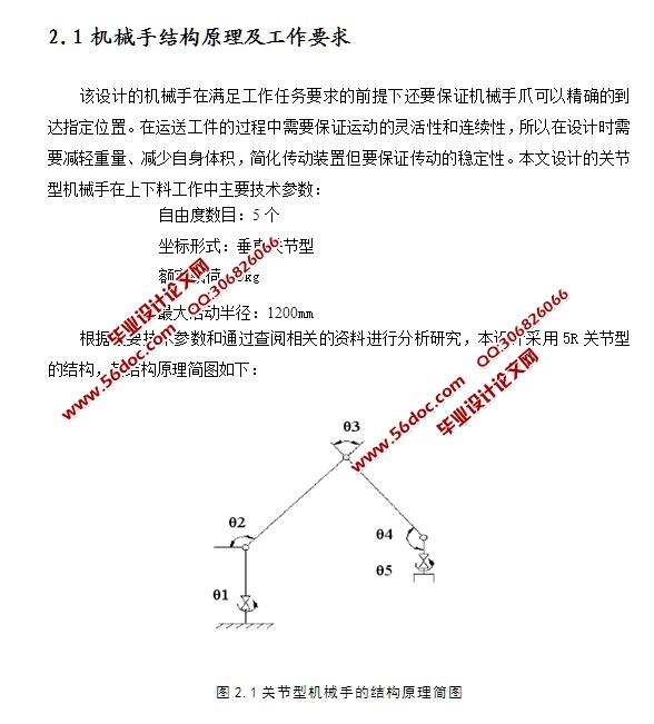
2.1 机械手结构原理及工作要求 5
2.2 机械手机构运动分析 6
2.3 机械手上下料工作空间轨迹分析 8
第三章机械手各结构设计 10
3.1 手爪的结构设计 10
3.1.1 手爪的设计要求 10
3.1.2 手爪的分类 10
3.1.3 手爪结构的确定 10
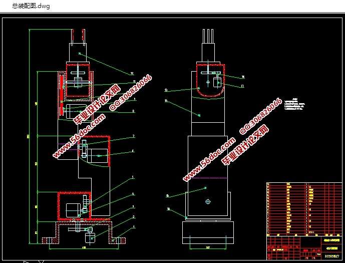
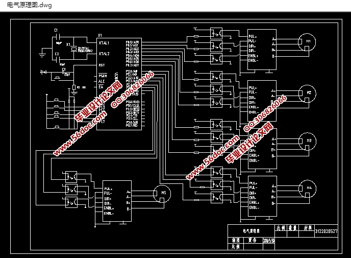
3.2 手腕的结构设计 11
3.2.1 手腕的设计要求 11
3.2.2 手腕的结构确定 11
3.3 手臂的结构设计 11
3.3.1 手臂的设计要求 12
3.3.2 大、小手臂的结构 12
3.3.3 小臂结构形式的确定 12
3.4 基座结构的设计 13
3.4.1 基座结构的设计要求 13
3.5 小臂后箱体结构设计 13
3.6 连杆结构设计 13
第四章机械手关键轴的校核 14
4.1 腕部输入轴的结构 14
4.2 腕部输入轴的校核 15
第五章机械手动力参数的计算 17
5.1 伺服电机的选型 17
5.1.1 初步估计机械手的质量 17
5.1.2 计算各个轴的转速和转矩 18
5.1.3 计算伺服电机的功率 20
5.2 锥齿轮设计 21
5.2.1 齿轮精度、材料 21
5.2.2 按齿面接触疲劳强度校核 21
5.2.3 按齿根弯曲强度设计 22
5.2.4 锥齿轮参数计算 23
5.3 同步带轮的设计 23
5.3.1 同步齿形带传动计算 23
5.3.2 带轮几何尺寸的计算 25
5.4 减速器的设计 26
5.4.1 减速器减速比的计算 26
5.4.2 减速器输出轴径的计算 27
结论 28
参考文献 29
致 谢 30
|