车床主轴箱箱体右侧10-M8螺纹底孔组合钻床设计(PLC控制)(含CAD图)(开题报告,论文说明书16000字,CAD图纸7张)
摘 要
本论文为加工主轴箱箱体右侧十个螺纹底孔的组合钻床的设计。
根据加工工件的尺寸图和生产要求,合理的拟定设计方案,完成该机床各部件及系统的设计,主要包括加工工序的制定,主轴、刀具的选择,多轴箱和滑台的合理选用,主轴箱内传动系统的设定,夹具的设计,以及制定液压和控制系统。设计过程中,在满足设计要求的同时,应该注意相互间的合理配合,这样才能从整体上把握组合机床的性能和结构。
为使设计符合现代化要求,该组合机床采用PLC控制系统来控制机床的工作,PLC控制是具有功能完善、通用灵活、简单易懂、操作方便和价格便宜等优点,这不仅满足了现代社会对生产的需要同时也体现了人性化设计的要求。
ABSTRACT
This thesis combination machine for design processing many stalks the box ten screw threads of rights the bore bed.
According to the processing work piece dimensional drawing and the production request, reasonable draws up the design proposal, completes this engine bed various parts and the system design, mainly includes the processing working procedure the formulation, the main axle, the cutting tool choice, the multi-axle-boxes and the sliding table select reasonably, in headstock transmission system hypothesis, jig design, as well as formulation hydraulic pressure and control system. In the design process, while satisfies the design request, should pay attention to mutually the reasonable coordination, like this can grasp the aggregate machine-tool overall the performance and the structure.
For making design to meet the modern request, and reshuffle to match the machine bed to adopt the PLC to control the system to control the revolving of machine bed, PLC control to have the function perfect, in general use and vivid, in brief and easily understand, operation convenience with price cheapness etc. Advantage, this not only satisfied the modern society to demand production also now the request of the humanized design.
1.2毕业设计的有关内容及计算:
(1)材料HT300:该加工件为主轴箱箱体,由表3-1 灰铸铁的牌号和力学性能 ,可知HT300型号的铸铁适于制造多轴机床主轴箱。
(2)硬度242HBS:查表3.2-3 灰铸铁铸件预计的机械性能及应用举例,有σb=290MPa,由硬度与抗拉强度间对应的经验公式,当σb>196MPa时
HB=RH(100+0.438σb)
灰铸铁相对硬度 RH=0.8~1.20
所以 HBmax=272HBS,
HBmin=182HBS,
查表7-24 组合机床设计中推荐的切削力、扭矩及功率计算公式的注解中 HB=HBmax-(HBmax- HBmin)/3
从而 HB=272-(272-182)/3
=242HBS
(3)重量估算
m=
=38Kg

目 录
前言 --------------4
1.毕业设计的目的和内容 --------------5
1.1通过毕业设计应达到的目的 --------------5
1.2毕业设计的有关内容及计算 --------------5
2.方案讨论及总体设计 --------------6
2.1 组合机床工艺方案的制定 --------------6
2.2 切削用量的确定 --------------7
2.3 确定切削力、切削转矩、切削功率--------------7
2.4 加工工序图 --------------8
2.5 液压滑台的设计计算 --------------9
2.6 加工示意图 --------------11
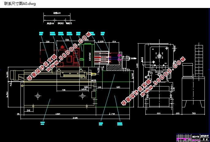
2.7 机床联系尺寸总图 --------------16
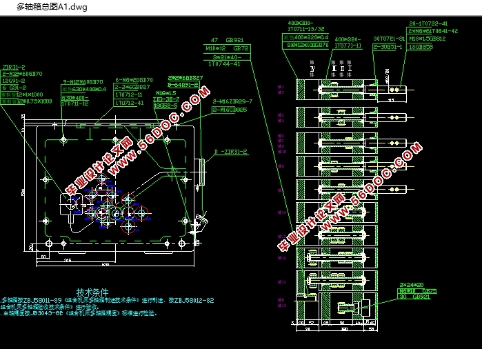
3.组合机床多轴箱设计 --------------21
3.1多轴箱的组成 --------------21
3.2 通用钻削主轴 --------------21
3.3通用传动轴 --------------22
3.4通用齿轮和套 --------------22
3.5主轴型式和直径、齿轮模数的确定 --------------22
3.6多轴箱的动力计算 --------------22
3.7 对多轴箱传动的一般要求 --------------23
3.8润滑泵轴和手柄轴的安置 --------------23
3.9 多轴箱传动系统拟定 --------------23
3.10 传动零件的校核计算 --------------27
3.11 传动系统的校核计算 --------------27
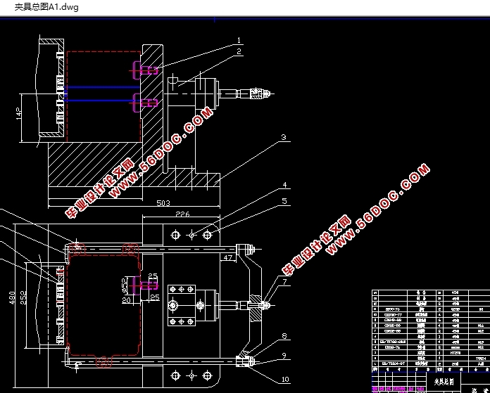
4.组合机床夹具设计 --------------29
4.1夹具的作用 --------------29
4.2具的组成 --------------29
4.3工件的定位 --------------30
4.4工件的夹紧 --------------30
4.5夹具总图 --------------30
5.液压系统的设计 --------------31
5.1 滑台原位停止 --------------31
5.2 滑台快进 --------------31
5.3 滑台工进 --------------31
5.4 滑台快退 --------------31
5.5液压系统图 --------------32
6.PLC控制系统设计 --------------33
6.1PLC工作原理 --------------33
6.2PLC的控制方式 --------------33
6.3动作循环图 --------------34
6.4端子分配图 --------------35
6.5梯形图 --------------36
6.6指令程序 --------------37
7.毕业设计体会 --------------38
8.致谢 --------------39
9.参考文献 --------------40
10.附录 --------------41
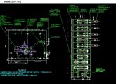
附录一:加工工序图
附录二:加工示意图
附录三:尺寸联系图
附录四:多轴箱设计图
附录五:夹具设计图
附录六:液压系统控制原理图
附录七:PLC控制图
|