重型数控加工装备传动系统结构设计(含CAD零件装配图)(任务书,开题报告,文献摘要,外文翻译,论文说明书11000字,CAD图7张)
摘要
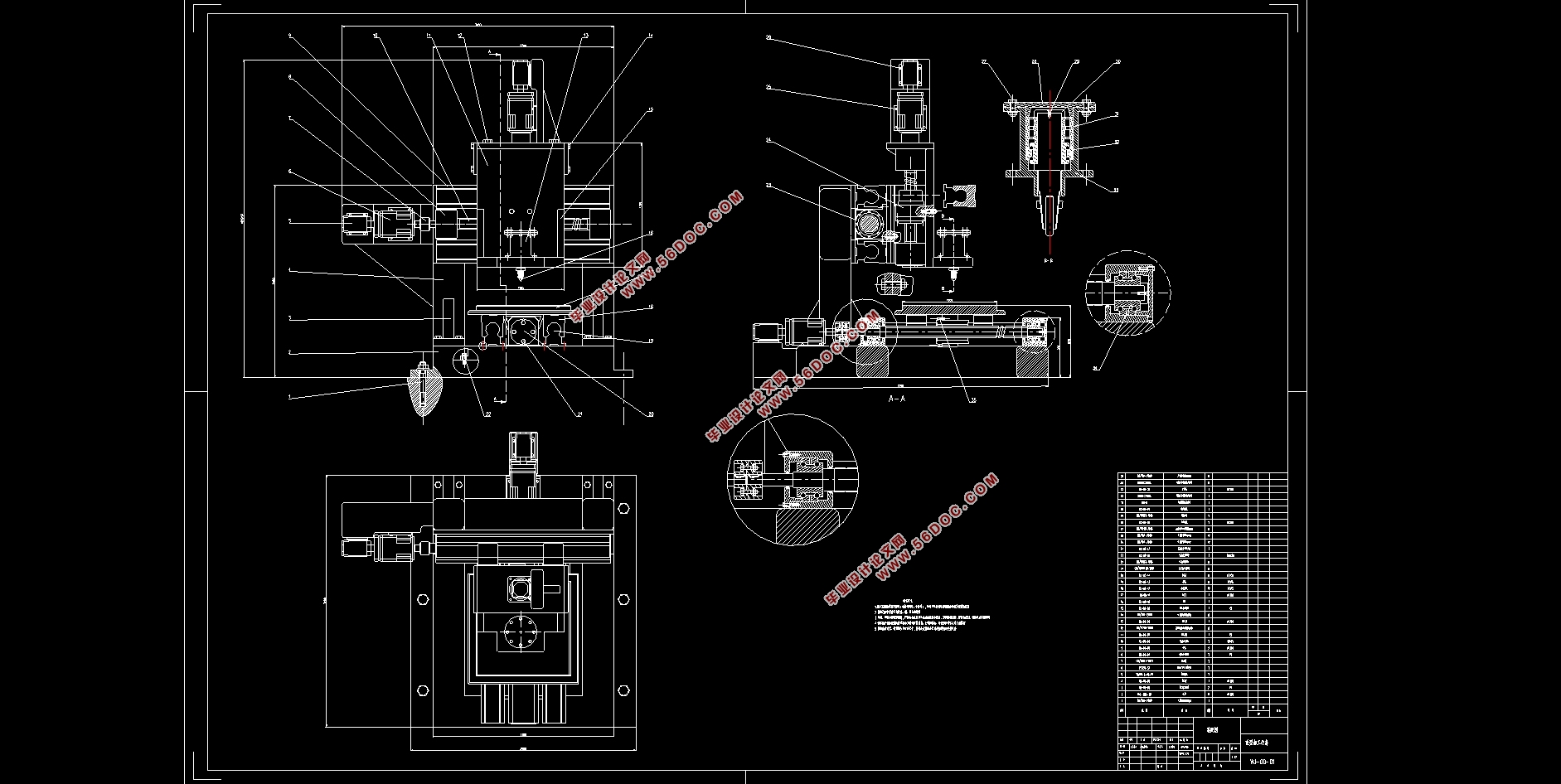
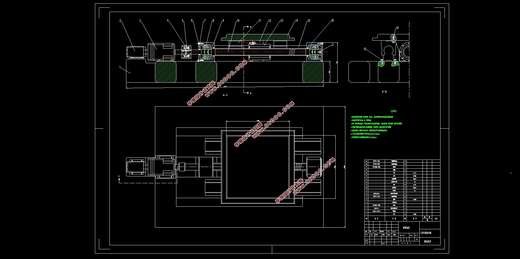
本文从重型数控龙门铣床起手,运用摆碾机的原理,借鉴国内外研究现状,给出了一种用于板材碾压成型的重型数控加工设备的设计方案,设计符合基本制造生产的要求。整个重型数控加工设备主要包括底座、龙门架、导轨、三轴伺服进给系统和工作台等组成部分。本次设计的重点在三轴进给系统,该系统由伺服电机驱动,经由行星齿轮减速器减速增矩后带动滚珠丝杆副旋转,进而转为刀具箱和工作台的轴向直线运动。参照学习用品设计了简易的刀具夹。
论文全面阐述了重型数控加工设备的结构形式和传动系统,对比挑选了伺服电机和滚珠丝杆作为传动系统的组成部分,重点讲解了滚珠丝杆副的构成和原理,并对重要受力部件进行了计算校核。
关键词:机床;传动系统;滚珠丝杆
Abstract
This paper starts from the heavy-duty CNC gantry milling machine, uses the principle of pendulum mill, draws on the research status at home and abroad, and gives a design scheme of heavy-duty CNC machining equipment for sheet metal forming, which meets the requirements of basic manufacturing. The entire heavy-duty CNC machining equipment mainly includes the base, gantry, guide rail, three-axis servo feed system and workbench. The focus of this design is on the three-axis feed system. The system is driven by a servo motor. After being decelerated and attenuated by a planetary gear reducer, the ball screw is rotated, which is converted into axial movement of the tool box and the table. The design reference learning kit is designed with a simple tool holder, and a two-way overrunning clutch is also installed on the Z-axis to prevent the Z-axis from slipping due to gravity.
The paper comprehensively expounds the structural form and transmission system of heavy-duty CNC machining equipment. The servo motor and ball screw are selected as the components of the transmission system. The composition and principle of the ball screw pair are explained, and the calculation and verification of important parts are carried out.
Key Words: machine tool; transmission system; ball screw
设计要求
通过以上分布设计,预计实现以下功能和要求:
机床三方向自由进给运动,
实现目标吨位,
刀具的装夹拆卸以及随动旋转,
理论上可实现,无原则性错误。
本次毕业设计给定的参数为:
工作台尺寸:1000×1000mm
最大碾压力:50吨(≈500kN)
目录
第1章 绪论 1
1.1背景 1
1.2数控加工技术 1
1.2.1数控机床的结构与原理 1
1.2.2数控机床的分类 2
1.3重型加工设备 3
1.4传统机床 4
1.5重型数控加工设备 4
1.6本章小结 5
第2章 重型数控加工设备传动设计方案 6
2.1设计要求 6
2.2设计理念 6
2.3本章小结 7
第3章 硬导轨的设计 8
3.1导轨设计要求 8
3.2导轨设计 8
3.2.1类型材料选择 8
3.2.2设计导轨截面 9
3.3导轨的润滑与防护 10
3.4本章小结 11
第4章 进给伺服传动系统 12
4.1系统方案设计 12
4.1.1执行元件 13
4.1.2传动机构 13
4.2滚珠丝杆计算选型 14
4.2.1滚珠丝杆导程 14
4.2.2当量载荷 14
4.2.3平均转速 15
4.2.4预计额定动载荷 15
4.2.5选择滚珠丝杠 15
滚珠丝杆轴承的选用 16
4.3伺服电机选型 17
4.4减速器设计选型 18
4.5滚珠丝杆使用与护理 19
4.6伺服进给系统结构图 20
4.7本章小结 20
第5章 机床刀具箱的设计 21
5.1刀具箱的设计要求 21
5.2刀具夹持方案分类 21
5.3刀具夹设计 23
5.3.1筒夹式 23
5.3.2 手动螺丝式 23
5.4主轴的设计 24
第6章 机床床身、龙门架与工作台 25
6.1床身设计 25
6.2 工作台设计 26
第7章 结论 27
参考文献 28
致谢 29
|