连杆精锪组合机床主轴箱设计(含CAD零件图装配图)
来源:56doc.com 资料编号:5D25496 资料等级:★★★★★ %E8%B5%84%E6%96%99%E7%BC%96%E5%8F%B7%EF%BC%9A5D25496
资料以网页介绍的为准,下载后不会有水印.资料仅供学习参考之用. 密 保 惠 帮助
资料介绍
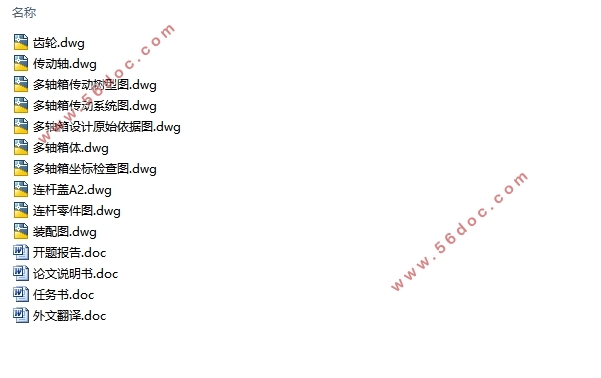
连杆精锪组合机床主轴箱设计(含CAD零件图装配图)(任务书,开题报告,外文翻译,论文说明书9000字,CAD图10张)
摘要
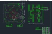
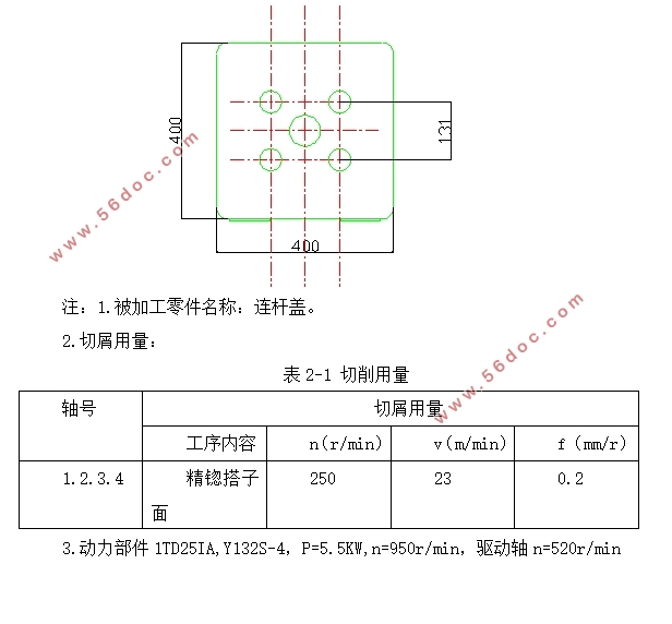
多轴箱是组合机床的重要专用部件。它是根据加工示意图所确定的工件加工孔的数量和位置、切削用量和主轴类型设计的传递各主轴运动的动力部件。其传动力来自通用的动力箱,与动力箱一起安装于进给滑台,可完成钻、扩、铰、镗、锪等加工工序。
多轴箱一般具有多根主轴同时对一系列孔系进行加工。
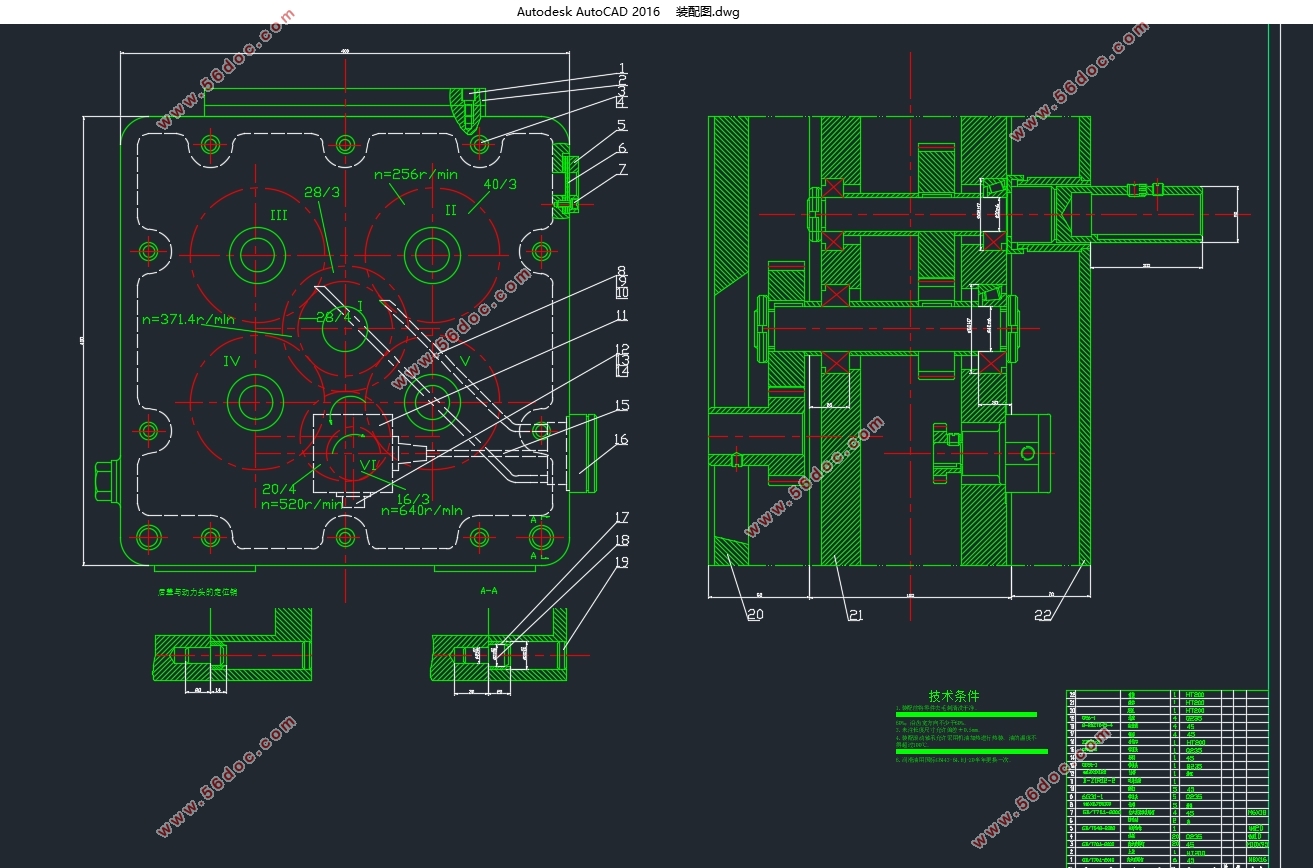
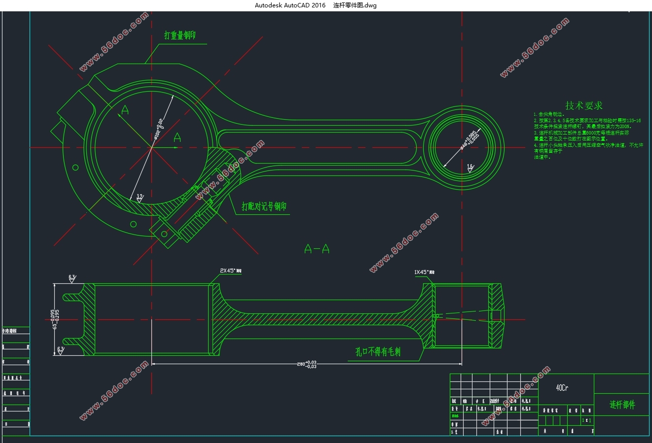
本课题是为了设计与加工连杆盖工艺凸台组合机床配套的多轴箱。最终和组合机床、夹具设计一起构成一个完整的加工工序。
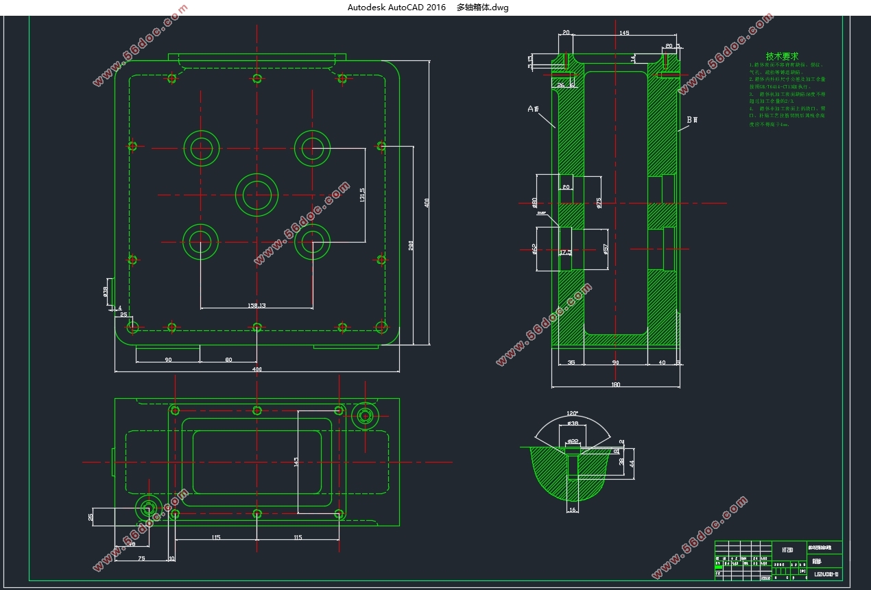
多轴箱的设计有一般设计法和电子计算机辅助设计法两种。本设计按一般设计法设计顺序:绘制多轴箱设计原始依据图;确定主轴结构、轴颈及齿轮模数;拟定传动系统;计算主轴、传动轴坐标;绘制坐标检查图;绘制多轴箱总图,零件图及编制组件明细表。
关键词:组合机床;夹具;多轴箱;连杆;原始依据图;齿轮;主轴;传动轴;总图;零件图。
Abstract
Multi-axle combination machine is an important special components. It is determined according to the processing of the workpiece diagram number and location of holes, cutting and spindle designed for the type of power transmission components moving each spindle. Its transmission power from the common power box, along with the power box mounted on the feed slide, to be completed by drilling, expanding, reaming, boring, countersinking and other machining processes.
Generally having a plurality of multi-axle spindles for machining holes of the range.
The project is to design and processing technology bosses rod cap portfolio tools supporting multi-axle box. Final and combined machine tools, fixture design together constitute a complete machining process.
The design of multi-axle general design method and electronic computer-aided design and French. The design of a general design method design sequence: Draw multi-axle design based on original drawing; determine spindle structure, journal and gear modulus; intended transmission; calculated spindle shaft coordinates; draw coordinate inspection figure; draw multi-axle total drawings, parts, assembly drawings and preparation of schedules.
Keywords: combination machine; fixture; multi-axle; link; primitive basis for drawing; gear; spindle; drive shaft; General Plan; Parts.
目录
摘要 I
Abstract II
目录 i
第一章、引言 1
1.1本课题研究背景。 1
1.2本课题研究现状。 1
1.3本课题结构,分类,组成,等。 2
1.4完成本课题设计的主要步骤及主要内容。 2
1.5本课题设计涉及到的设计要求与特点,方法,软件工具等。 3
第二章.绘制多轴箱设计原始依据图 5
第三章、多轴箱传动设计 7
3.1对多轴箱传动系统的一般要求 7
3.2拟定多轴箱传动系统 7
3.2.1确定主轴分布类型 7
3.2.2确定驱动轴转速转向及其在多轴箱上的位置 8
3.2.3用最少的传动轴及齿轮副把驱动轴和各主轴联系起来 8
3.3主轴直径的选择 13
3.4传动轴直径的选择 13
3.5轴承类型的选择 14
3.6润滑方式的选择 14
第四章、多轴箱坐标计算、绘制坐标检查图 15
4.1选择加工基准坐标系XOY,计算主轴、驱动轴坐标 15
4.2计算传动轴的坐标 15
4.3验算中心距误差 15
4.4.绘制坐标检查图 16
第五章、绘制多轴箱总图及零件图 18
5.1多轴箱总图设计 18
5.2多轴箱零件设计 19
第六章、主轴和传动轴强度校核 20
6.1主轴强度校核 20
6.2传动轴强度校核 21
结语 23
参考文献 24
致谢 26
|