工业机器人夹具及其物料输送系统的设计(附CAD图,PROE三维图)
来源:56doc.com 资料编号:5D25554 资料等级:★★★★★ %E8%B5%84%E6%96%99%E7%BC%96%E5%8F%B7%EF%BC%9A5D25554
资料以网页介绍的为准,下载后不会有水印.资料仅供学习参考之用. 密 保 惠 帮助
资料介绍
工业机器人夹具及其物料输送系统的设计(附CAD图,PROE三维图)(论文说明书11000字,CAD图9张,PROE三维图)
摘 要
当代,制造业的生产规模日益扩大,批量化生产要求越来越高,越来越看重自动化生产,自动化生产可以极大的提高生产的性价比。机器人作为代替人力的工具,具有效率高,精确的特点,而机器人工装夹具是重要的一环,而与生产相匹配的物料输送系统更是不可或缺的,它保障了流水线生产的效率进行。
本文首先对机器人工装夹具和物料输送系统的定义、意义、研究重点、研究状况进行了介绍;然后通过机器人选型完成夹具设计以及物料输送系统的设计,其中夹具主要集中于夹具的选型以及夹具的结构、力学分析,最后完成夹具图纸的制作。物料输送系统通过控制、电气和机械三个方面进行设计,控制部分主要通过PLC实现,并通过PLC完成系统的接线等工作;机械部分主要是电机、轴、带等的选用。
关键词:夹具 物料输送 结构 控制
The design of Industrial Robot Fixture and Material conveying System
Abstract
In the modern large-scale manufacturing industry, to improve production efficiency and ensure quality, the enterprises pay more attention to the degree of automation of production processes. The robot has the advantages of high efficiency and high accuracy as a alternative of the human beings. And the fixture plays a important role of it, as well as the material conveying system for the reason that it ensure the the efficiency of the production line.
This paper firstly introduce the definition, significance and research status of industrial robot fixture and material conveying system, and then complete the design of it by chose a robot. The paper mainly focus on the selection, structure and analysis of fixture to design it and finish the drawings at last. The material conveying system is designed through three aspects of control, electrical and mechanical, control part is mainly realized by PLC, mechanical part mainly focus the choses of the motor, shaft and conveyors.
Key Words: fixture material-conveying structure control
设计目标
本文通过设计目标是工业机器人夹具和相应的物料输送系统,使得工作效率大大提高,减小生产成本。该设计可以用于完成机械加工中心自动上下料、自动运输原料、自动存储产品的功能。
2.2 选择夹具的类型及夹紧装置
夹具的工作对象是夹取部位为圆柱体的工件,夹取重量为20Kg。
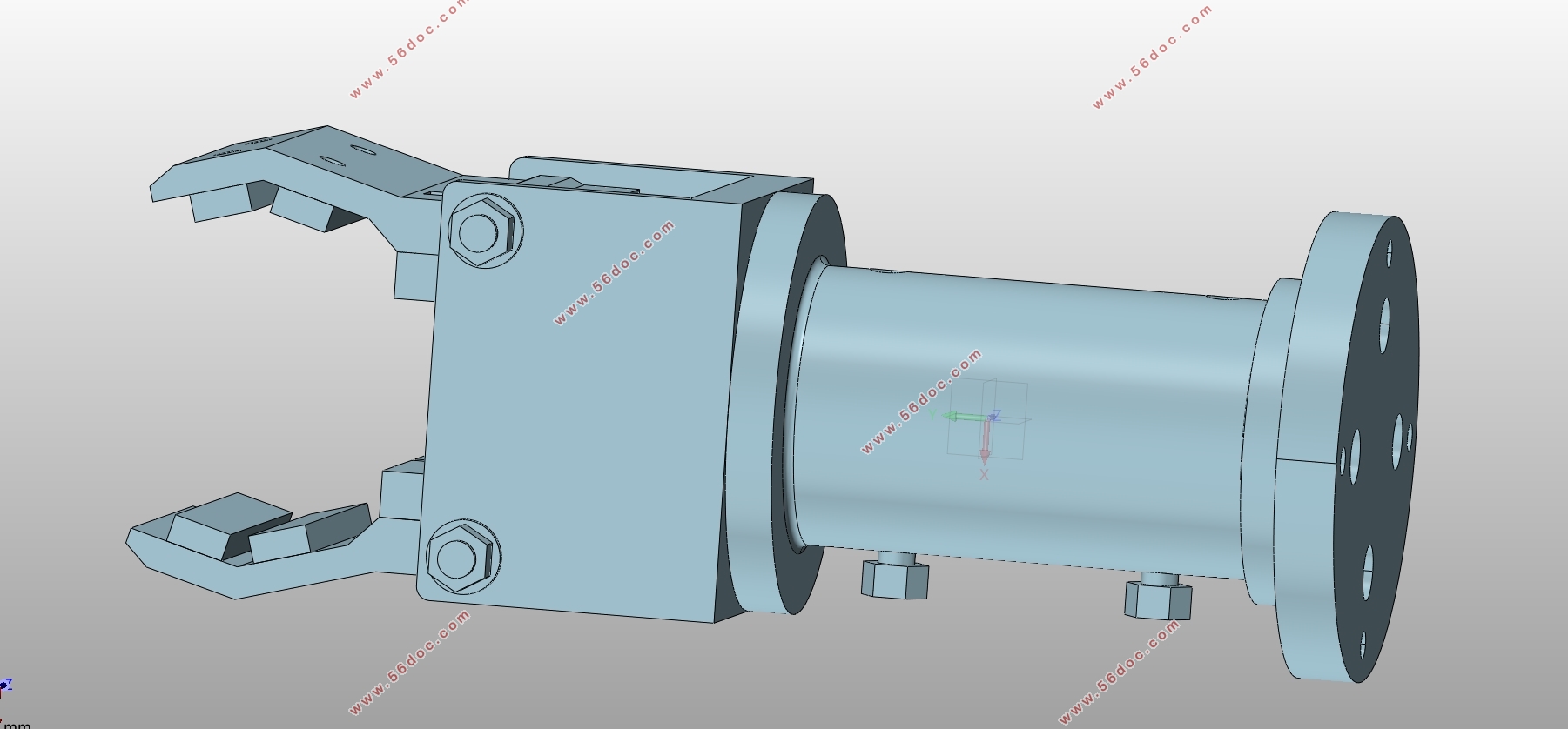
一般来说,夹具的型号很多,但工作原理却基本相似,一种是通过物理夹取的方式,模仿人手抓取工件,另一种是通过电磁铁等方式吸附工件。本次设计中工件的抓取部分为圆柱,而圆柱表面不利于电磁铁牢牢吸住工件,所以吸附式的夹具不予采用。而另一种模仿人手抓取的夹具又可以根据加持方式分为两大类:回转和平移型。平移型的优势在于加持部分通过平移方式夹住工件,基本没有误差,适合加持箱体形状的工件;但也有着体积太大导致夹具过于臃肿的缺点,这与我们的设计要求是不相吻合的。所以本次设计采用的方案是回转型夹具。
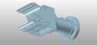
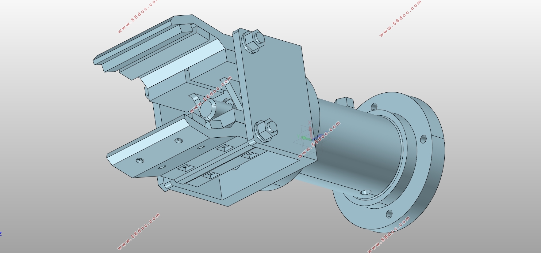
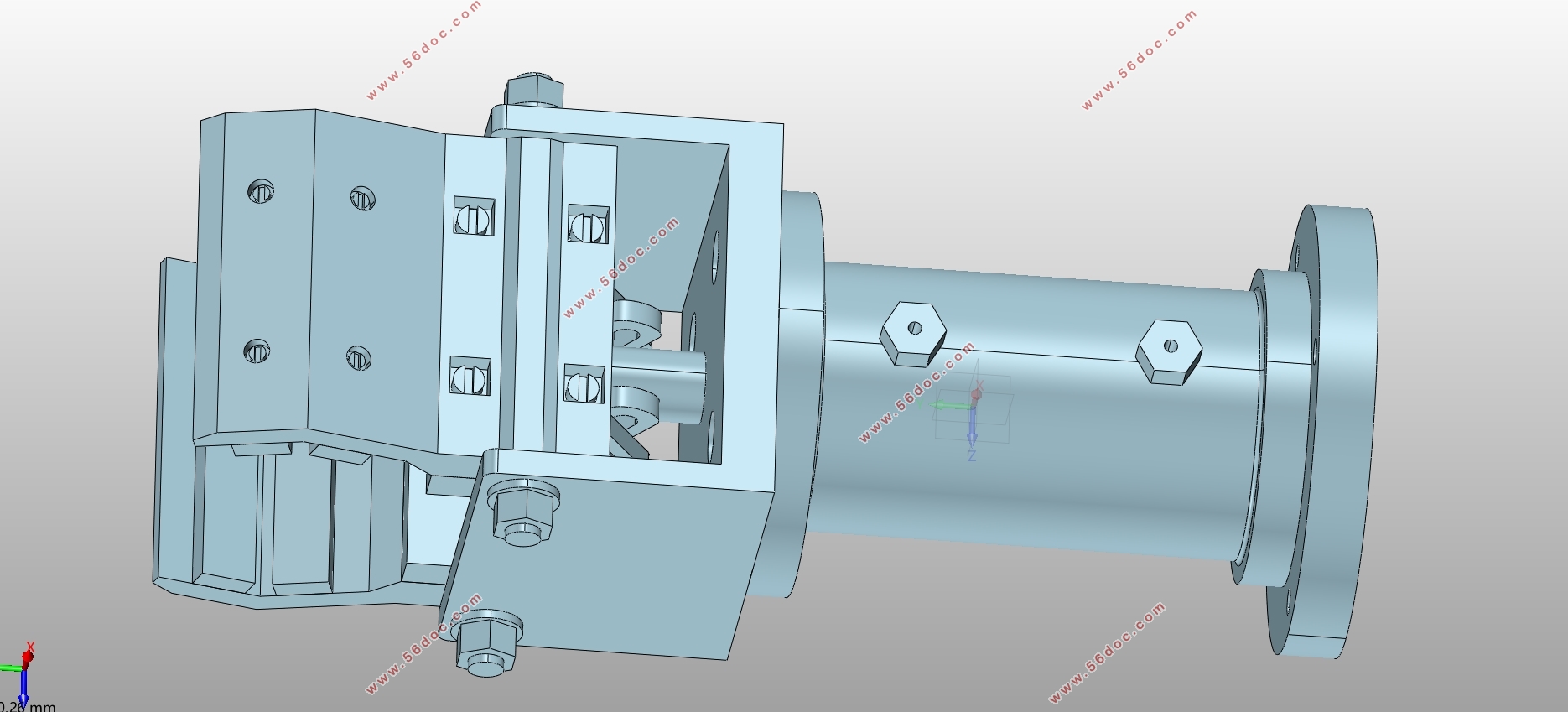
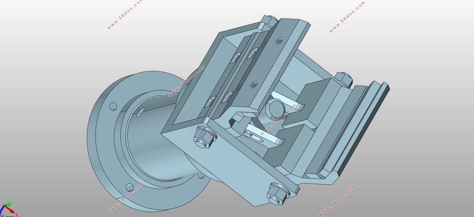
本次的设计是通过液压作为动力,由液压带动活塞杆,通过连接装置使得夹爪绕轴进行回转运动进而夹住工件。下图即为本次设计的手爪形式,这样的手爪还有着可以自动定

目录
摘 要 Ⅰ
ABSTRACT Ⅱ
第一章 引言 1
1.1 机器人夹具及物料输送系统概述 1
1.2 机器人研究现状 2
1.3 机器人及物料输送系统发展趋势 3
1.4 设计目标 3
第二章 夹具设计 4
2.1 夹具设计基本要求 4
2.2 选择夹具的类型及夹紧装置 4
2.3 夹具的结构分析 6
2.3.1 夹具的力学分析 6
2.3.2 夹紧力和驱动力的计算 7
2.3.3 液压缸的结构计算和校核 10
2.3.4 液压缸设计中应注意的问题 11
第三章 物料输送系统的设计 12
3.1 控制系统概述 12
3.2 控制系统设计 13
3.2.1 输送基本动作 13
3.2.2 流程图 14
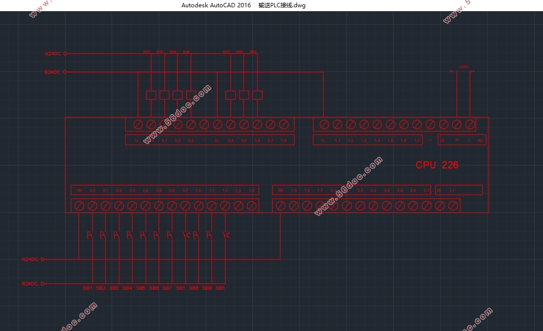
3.2.3 接线图 15
3.2.4 PLC梯形图 15
3.3 机械系统设计 17
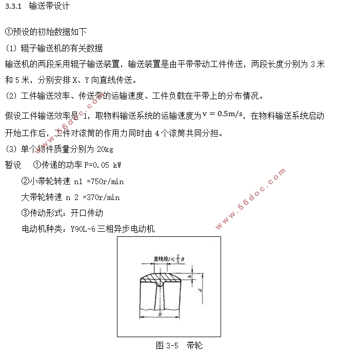
3.3.1 输送带设计 17
3.3.2 辊子设计 20
3.4 三相异步电动机的计算与选型 23
3.5 辊子输送机技术要求 24
3.5.1 辊子机架 25
3.5.2 表面涂装 26
3.5.3 整机安装 26
3.6 气压系统 27
3.6.1 直径 27
3.6.2 壁厚 27
3.6.3活塞杆稳定性及挠度验算 28
3.6.4 缓冲计算 29
3.6.5活塞杆的承载能力 30
3.6.6气压系统图 31
第四章 设计总结 32
参考文献 33
致谢 35
|