数控磨齿机床主轴箱传动系统三维建模(含CAD零件图装配图,PROE三维图)(任务书,论文说明书12000字,CAD图15张,PROE三维图)
摘要
随着我国工业的快速发展,特别是2015年以来国家提出《中国制造2025》发展战略以来,制造业作为国民经济的发动机,正渐渐得到国家的重视,到2018年,改革开放已经快40年,过去这段时期,我国制造业持续快速发展,形成种类齐全、独立完整的产业体系,不过关键技术还落后西方工业强国。国内很多工程机械对齿轮的要求越来越高,滚齿、剃齿等传统加工工艺不能满足未来对于齿轮的要求,很多国内齿轮加工企业开始引入磨齿这一工序来提高齿轮的精度。
成形磨削能很好地完成齿轮的磨削加工,达到工艺要求,为了降低机床的设计成本,缩短设计的时间,利用计算机辅助设计技术,通过计算机软件制作并进行实物设计、分析与参数优化,可提高加工质量与效率,作为磨齿机关键部分的主轴系统,其加工零件的精度直接影响产品的质量,市场上大都是采用电主轴来减轻传统的齿轮传动带来的加工误差,但为了最大程度减小主轴误差,对数控磨齿机主轴箱进行三维建模分析。
本文研究的对象是南京工大数控有限公司SKMC系列数控成形磨齿机。文章开头介绍国内外磨齿机的发展情况与主轴系统的发展,然后对SKMC系列磨齿机性能特点与参数进行介绍,对主轴箱进行参数设计与校核,吗,最后通过Pro/e软件对主轴箱进行建模与装配,并通过分解图了解各零件在主轴箱中的相对位置。
关键字:磨齿机主轴箱三维建模传动系统
Three-dimensional Modeling of Spindle Drive System of NC Grinding Machine
ABSTRACT
With the rapid development of China's industry, especially since the country put forward the development strategy of “Made in China 2025”, the manufacturing industry has gradually gained the attention of the country as the engine of the national economy. By 2018, reform and opening up has been almost 40 years. In the past period of time, China’s manufacturing industry continued to develop rapidly, forming a complete, independent and complete industrial system. However, key technologies still lag behind Western industrial countries. Many domestic construction machinery have higher and higher requirements for gears. The traditional machining processes such as hobbing and shaving do not meet the requirements for future gears. Many domestic gear processing companies have begun to introduce grinding gears to improve the accuracy of gears.
Forming grinding can well complete the grinding process of gears and achieve the technical requirements. In order to reduce the design cost of the machine tool and shorten the design time, computer-aided design technology is used to create and carry out physical design, analysis and parameter optimization. The machining quality and efficiency can be improved. As the spindle system of the key part of the gear grinding machine, the precision of its machining parts directly affects the quality of the products. Most of the spindles in the market use the electric spindle to reduce the machining error caused by the traditional gear transmission, but in order to reduce the error of the spindle and perform three-dimensional modeling analysis on the headstock of the CNC gear grinding machine.
The object of this article is the Nanjing Industrial University CNC Co., Ltd. SKMC series CNC forming grinding machine. The article begins with introduction of the development of gear grinding machines at home and abroad and the development of spindle systems. Then it describes the performance characteristics and parameters of the SKMC gear grinding machines, and design and check the parameters of the spindle heads. Finally, the Pro/e software is used to model and assemble, and an exploded view shows the relative position of each part in the headstock.
Key Words:Grinding machine;Spindle box;3D modeling;Transmission system
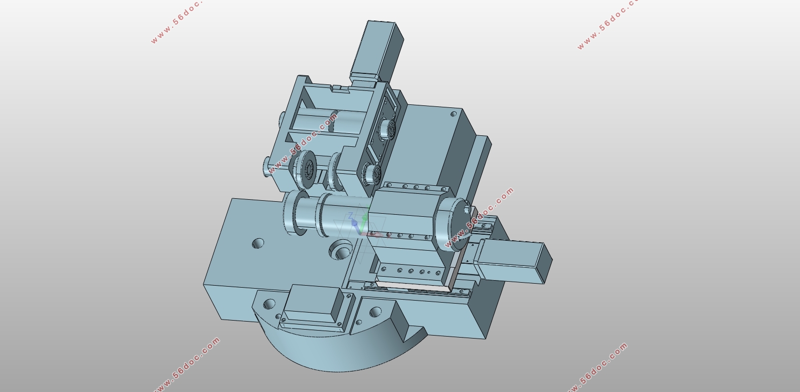
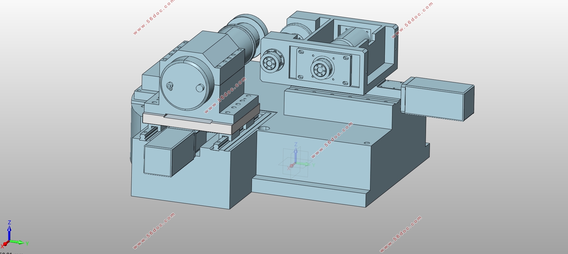
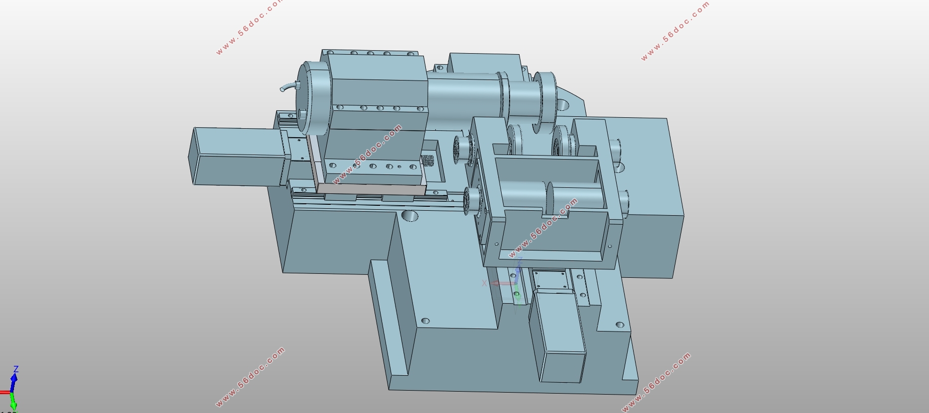
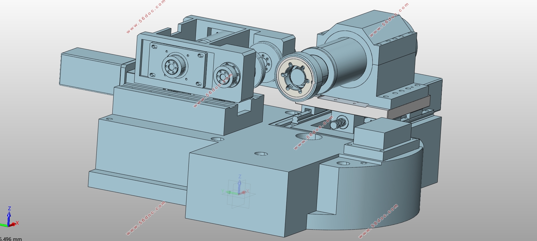
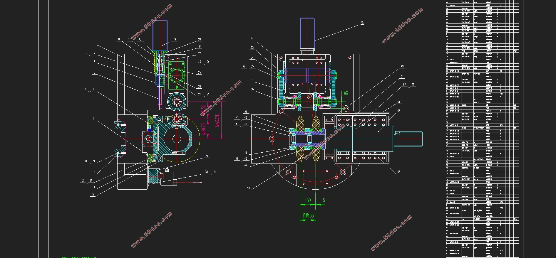
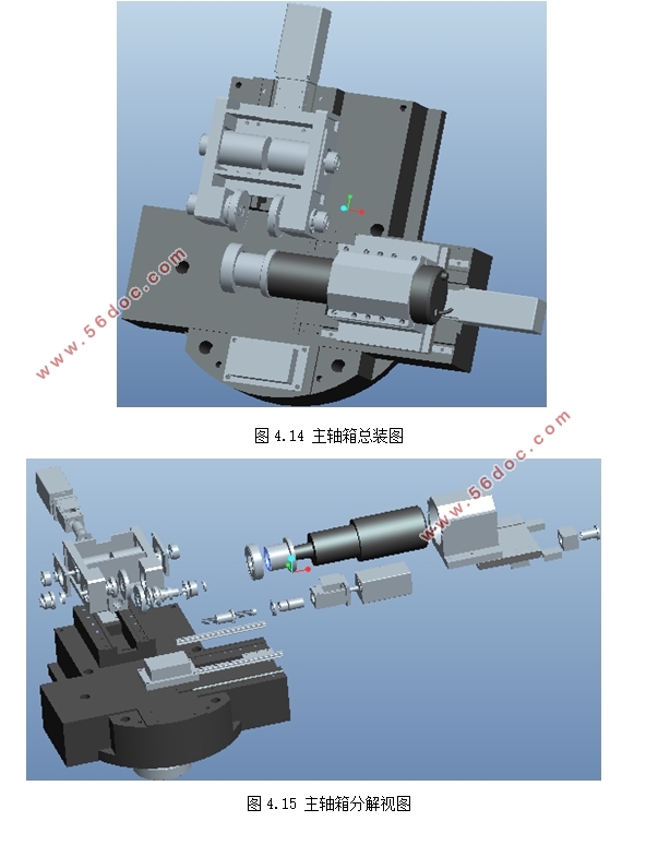
本文研究对象是工大数控研制的SKMC系列数控成形磨齿机的主轴箱,通过对磨齿机参数化建模,能了解其加工的特点,运用Pro/e软件进行三维建模,通过对二维图纸的了解,进行主轴箱各组成零件的三维建模,然后根据总装图进行主轴箱的装配,通过这个过程对数控磨齿机组成更加了解,对磨齿机工作原理以及主轴、砂轮如何进行磨削加工得到认识。
本设计通过对已知磨齿机结构主轴箱建模与分解,了解其组成结构与参数,通过实体建模可对轴的力学性能进行分析,并可通过仿真来优化主轴箱的结构与参数,三维建模能通过计算机软件对磨齿机进行实际制造前的分析,对提高主轴的稳定性、结构的合理性、以及实际运转中的精度等方面促进作用,便于研发制造磨齿机主轴系统及完整的磨齿机。
2.1 磨齿机的整体布局
2.1.1技术参数
SKMC-3000数控成形磨齿机可加工的内、外齿及斜齿的最大模数为30mm,螺旋角±45°,最大直径为3000mm;回转工作台直径2000mm,允许最大承重30000kg;成形磨削进给速度达4000mm/min;加工齿轮的主要精度指标达GB4级,MTBF达到900h。其技术参数如下表2-1。
表2-1 数控成型磨齿机技术参数表
2.1.2机床结构与坐标系
如图2-1所示,立式布置已经成为很大大型与中型磨齿机的主要布置方式,主要组成结构包含有转台、床身、立柱、托板和磨头;X、Y、Z、A、C、W、SP1、SP2、SP3轴组成了磨齿机的轴线[10]。图2-2是磨齿机床的坐标系图,其中,X轴为砂轮的径向方向,通过床身导轨机构实现该运动;Z轴为砂轮的垂直移动方向,同意通过立柱上的滚珠丝杠实现运动,C轴提供齿轮的回转运动,完成各个齿面的磨削加工,A轴是由电机驱动完成实现主轴箱砂轮的旋转,W与Y轴分别实现金刚轮垂直于切向的运动,SP1砂轮主轴运动有电机驱动,SP2、SP3是表示金刚轮的旋转方向,通过电机驱动、皮带传送实现旋转功能。由机构图可知,此磨齿机主轴由两部分组成:一是砂轮修正系统,主要由X、Y、Z、A、C、SP1三轴功能实现到达;二是磨削系统,主要由Y、W、SP1、SP2、SP3组成。砂轮的修正系统,使砂轮在Y和W轴构成的平面坐标系里运动,金刚石滚轮用于对砂轮轮廓进行修整[11]。
目录
摘要 I
ABSTRACT II
目录 IV
第一章绪论 1
1.1 课题背景和意义 1
1.2 磨齿加工介绍 2
1.2.1 展成磨削 2
1.2.2 成形磨削 3
1.3 成形磨齿机国内外现状 4
1.3.1 磨齿机国内外发展 4
1.3.2 主轴系统国内外发展 5
1.4 本文课题内容 6
第二章 SKMC数控成型磨齿机 7
2.1 磨齿机的整体布局 7
2.1.1 技术参数 7
2.1.2机床结构与坐标系 8
2.2 磨齿机加工原理 9
2.2.1 往复式成形磨削 9
2.2.2 连续修整成形磨削 9
2.2.3 缓进给磨削 10
2.3 磨齿机特点 10
2.3.1 精密进给技术 11
2.3.2 精密转台技术: 11
2.3.3 主动精密制造与误差补偿技术 12
2.3.4 机械化动态优化设计 12
2.4 磨齿机功能应用 12
第三章主轴箱参数设计 13
3.1 电机选型 13
3.1.1 初始参数 13
3.1.2 磨削力计算 13
3.1.3 磨削功率计算 14
3.1.4 确定型号 14
3.2 电主轴设计 16
3.2.1 电主轴直径 16
3.2.2 轴的结构工艺性 17
3.3 轴承的选择 18
3.3.1 滑动轴承 18
3.3.2 滚动轴承 19
3.4 成本分析 19
第四章主轴箱零件的实体建模与装配 21
4.1 实体建模技术 21
4.1.1 Pro/e软件简介 21
4.1.2 二维图纸三维化 21
4.2 主要零件的建模 23
4.2.1 箱体建模 24
4.2.2 主轴建模 24
4.2.3 修正电机支架建模 25
4.2.4 其余零件建模 26
4.3 磨齿机主轴箱装配 27
4.3.1 软件的装配与分解命令 27
4.3.2 装配主轴箱 28
结语与展望 31
参考文献 32
致谢 34
|
