变刚度柔性转子装置设计(含CAD零件图装配图)
来源:56doc.com 资料编号:5D27192 资料等级:★★★★★ %E8%B5%84%E6%96%99%E7%BC%96%E5%8F%B7%EF%BC%9A5D27192
资料以网页介绍的为准,下载后不会有水印.资料仅供学习参考之用. 密 保 惠 帮助
资料介绍
变刚度柔性转子装置设计(含CAD零件图装配图)(论文说明书13000字,CAD图11张)
摘 要
机器运转时,转子系统常常发生振动。振动的害处是产生噪声,减低机器的工作效率;严重的振动会使原件断裂,造成事故。如何减少转子系统的振动是设计制造旋转机器的重要课题。因此,确定转子系统的各阶临界转速十分重要,采用实测与理论计算相结合是获得准确的临界转速的有效方法。
本文采用影响系数法计算转子轴的二阶临界转速,通过计算机化的“信号采集与分析系统CRAS”测得转子轴的实际二阶临界转速。在此基础上进行转子轴的设计和校核,根据轴选择了深沟球轴承并验证了轴承的寿命合格,选择了凸缘联轴器并校核,完成了试验台的整体设计。
关键词:转子试验台,临界转速,设计校核
Abstract
When the machine is running, the rotor system often occur vibration. The harmful effects of vibration are produce noise and reduce the efficiency of the machine; seriously vibration will make the machine break. How to reduce the vibration of the rotor system is an important issue in design and manufacture of rotary machines. Therefore, it’s very important to determine the rotor system critical speed, using a combination of measured and calculated is an effective method to obtain critical speed.
The Article use influence coefficient method to calculate the second-order critical speed of rotor shaft, through the computerized "signal acquisition and analysis system CRAS" measure the actual second-order critical speed of rotor shaft. On this basis designed the rotor shaft and revised it. According to the rotor, chose the deep groove ball bearing and validated the life-span is eligible. Select and check the flange coupling, accomplished the whole design of the rotor test-bed.
Key words: rotor test-bed; critical speed; Design verification
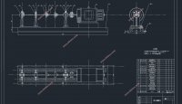
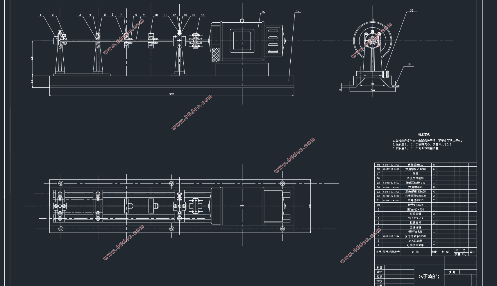
本试验台采用直流并励电动机驱动,电机轴经联轴器直接驱动转子,结构简单,调速范围宽,且平稳可靠。
组成及主要技术指标:
1、直流并励电动机:额定电流:2.5A 输出功率:250W
2、调速器:调速范围:0~10000转 外形尺寸:260×170×170 mm
3、试验台:长:1200mm 宽:108mm 高:145mm 重: 45kg
试验台包括:转轴(共配有4根)直径:Φ9.5mm
长度:320mm 3根
500mm 1根(专用于作油膜振荡)
最大挠曲不超过0.03mm
4、转子(共配有六只),分为 76×25mm、 76×19mm两种规格(各3只): 76×25mm,重量为800g
76×19mm,重量为600g(可根据实验需要选用)
5、配有刚性联轴节和半挠性联轴节供选用。
6、试验台最多可安装三跨转子,用Ф8涡流传感器测量,测点数随转子数而定,每个转子可安装x及y方向各一个测点。
7、试验临界转速因跨度、转子质量及位置等因素而各异,参考数据如下:
使用320mm转轴,跨度为250mm,当一根轴上安装两个转子时,其一阶临界转速约为4400rpm。
使用500mm转轴时,安装两个转子,其一阶临界转速约为2400rpm。
本实验选500mm转轴, 76×25mm、 76×19mm转子各一个
目录
摘录 Ⅰ
Abstract Ⅱ
第一章 绪论 1
1.1课题研究背景和意义 1
1.2转子在工业中的应用 1
1.2.1转子的分类 1
1.2.2转子在工业中的应用 2
1.3临界转速 2
1.3.1临界转速的定义与危害 2
1.3.2临界转速计算方法 3
1.3.3计算机在柔性转子轴的临界转速实验教学中的应用 4
1.3.4测试系统组成 4
1.4转子的平衡 5
1.4.1定义 5
1.4.2转子平衡的选择与确定 6
1.5平衡机 7
1.5.1平衡机的定义 7
1.5.2平衡机的分类 7
1.5.3柔性转子现场平衡方法 7
第二章 临界转速的计算 10
2.1影响系数法 10
2.2转子轴的临界转速计算 11
第三章 转子轴临界转速实验 13
3.1实验意义 13
3.2转子试验台概述 13
3.3组成及技术参数 13
3.4实验装置与原理 14
3.4.1振动试验接线示意图 14
3.4.2柔性转子振动模拟试验台 14
3.4.3计算机化的数据采集与信号分析系统 15
3.4.4实验原理 16
3.4.5实验步骤 17
3.4.6实验数据与分析 18
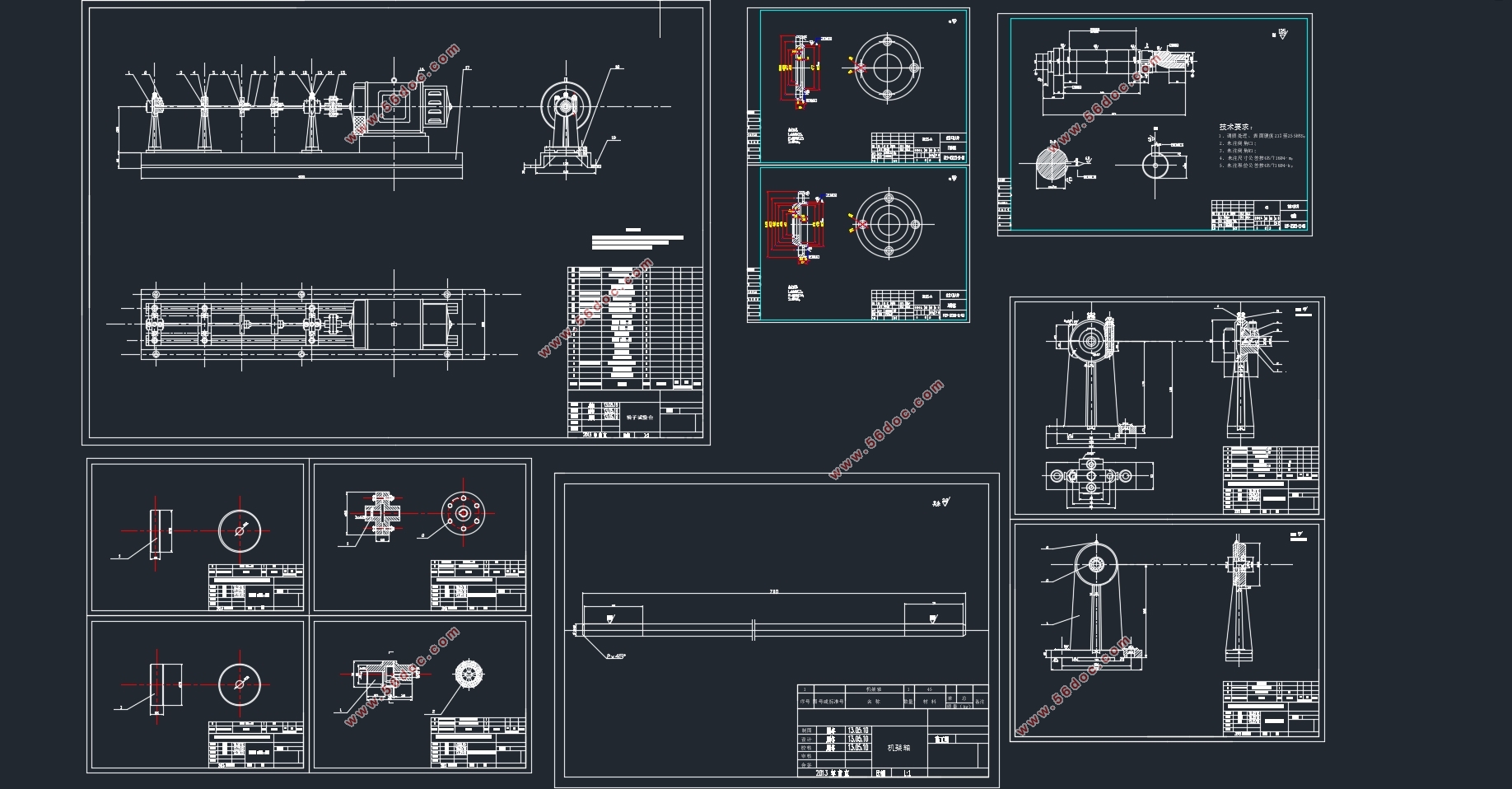
第四章 转子实验台的设计 25
4.1轴的设计 25
4.2轴的校核 26
4.3轴承的选用与校核 28
4.4联轴器的选择 30
4.5其余零部件设计 31
致谢 32
参考文献 33
|