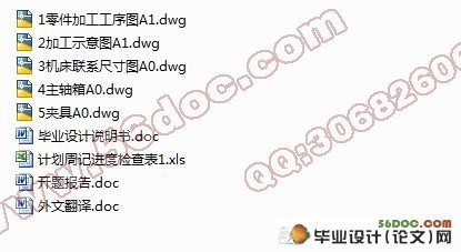
柴油机汽缸体两端面铣削专机设计(含任务书,开题报告,外文翻译,毕业论文说明书18500字,进度检查表,CAD图纸5张)
摘 要
本课题是柴油机汽缸体两端面铣削专机设计,主要是完成机床夹具设计、组合机床总体设计、组合机床主轴箱设计。根据柴油机汽缸体的结构特点、加工部位、尺寸精度、表面粗糙度及生产率等要求,确定该机床为卧式组合机床;考虑工件尺寸精度,表面粗糙度,切削的排除生产率等因素,选用硬质合金不重磨式面铣刀;根据工件的尺寸、特点及其材料选择切削用量;然后,再经过切削用量来确定组合机床的通用部件;最后进行组合机床的总体设计。由于是铣削柴油机汽缸体的两端面,则夹具的设计可以采用“一面两销”定位,手动夹紧,一次装夹加工汽缸体两端面,保证加工精度,提高生产率;根据工作将受到切削力来计算夹紧力;再根据夹紧力来选择确定夹紧装置的专用部件。
在设计之中,尽量使用通用件,减少制造成本,增加经济效益。通过本次设计可以达到的效果是:所设计的夹具及主轴箱能满足所需的质量要求,使用时安全可靠,拆装方便,易于维修。
关键词:组合机床;汽缸体;铣刀;夹具
Abstract
This topic is called a diesel engine at both ends of the cylinder block face milling plane design, mainly including the completion of jigs and fixtures design, the combination of the overall machine design and machine tool spindle box design. According to the structural characteristics of the diesel engine cylinder block, the processing site, dimensional accuracy, surface roughness and productivity requirements, it can be determined that the machine is a horizontal combination of machine tools; considering the accuracy of the workpiece dimensions, surface roughness, cutting negative factors such as productivity, the hard-alloyed throw-away grinding-face milling is chosen; cutting amount is selected according to the size of the workpiece. characteristics and material selection; then, by the cutting amount we determine the combination of general machine parts; Finally, the overall design of the machine is carried out. Due to both end faces of the milling diesel engine cylinder block, the design of the fixture can employ "the two sells" positioning, manual clamping, a fixture worked both ends of the cylinder block surface to ensure accuracy and improve productivity; clamping forces will be calculated through the cutting force; and determine specific parts of the clamping device according to the clamping force.
In such a design, one should make use of common parts to reduce manufacturing costs and increase economic benefits. The design can achieve the effect that the design of the fixture and spindle box can meet the quality requirements and it guarantees safe and reliable use, easy disassembly and easy maintenance.
Key words: combination machine tools; The cylinder body; Milling cutter;fixture
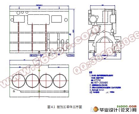
被加工零件分析
被加工零件:柴油机气缸体
材料:HT250
硬度:187—255HBS
年产量:7万件
加工部位:两端面
加工要求:汽缸体两端面粗糙度被加工到6.3 m ,两端面尺寸至582±0.3mm
目 录
摘 要 III
Abstract IV
目 录 V
1 绪论 1
1.1 课题来源 1
1.2 国内外的发展状况 1
1.3 指导思想和设计要求 2
2 总体方案论证 3
2.1 被加工零件分析 3
2.2 工艺方案的制定 3
2.3 加工设备方案选择 3
2.4 确定机床总体布局 4
3 切削用量的选择及计算 5
3.1 切削刀具的选择 5
3.2 切削用量的选择 5
3.3 切削力、切削转矩、切削功率的确定 5
4 组合机床总体设计 8
4.1 被加工零件工序图 8
4.2 加工示意图 9
4.3 机床联系尺寸图 10
4.3.1 动力部件的选择 10
4.3.2 滑台及相配底座的选择 11
4.3.3 确定机床的装料高度H 11
4.4 机床生产率计算卡 11
4.4.1 理想生产率Q 11
4.4.2 实际生产率Q1 12
4.4.3 机床负荷率ŋ负 13
4.4.4 编写机床生产率计算卡 14
5 主轴箱设计 15
5.1 主轴及传动轴结构设计 15
5.2 主轴箱传动计算 16
5.2.1 传动比分配 16
5.2.2 传动系统设计及齿轮的排布 17
5.3 主轴箱的润滑及油泵轴的确定 18
5.4 轴的计算及主轴校核 18
5.5 齿轮的校核 20
5.6 轴承的选择与校核 21
6 夹具设计 24
6.1 定位误差分析计算 24
6.2 夹紧装置设计 25
6.3 夹紧力的计算 25
6.4 夹具零部件的设计 27
6.4.1 夹具体的设计 27
6.4.2 支座的设计 28
6.4.3 支承板的设计 28
6.4.4 螺杆的设计 29
6.4.5 支承轴的设计 30
6.4.6 压板的设计 30
6.4.7 导向板的设计 31
7 液压系统设计 32
7.1 负载分析 32
7.2 负载图和速度图的绘制 32
7.3 液压缸主要参数的确定 32
7.4 拟定液压系统原理图 35
7.4.1 液压系统的工作要求的确定 35
7.4.2 拟定液压系统图 35
7.5 计算和选择液压元件 37
7.5.1 确定液压泵的最高工作压力 37
7.5.2 确定液压泵流量 38
7.5.3 选择液压泵规格 38
7.5.4 计算油泵需要的电机功率 38
7.6 阀类元件的选择 38
7.7 油管的确定 39
7.8 确定其它辅助装置 39
7.9 发热及油箱容量计算 39
8 结论与展望 40
8.1 结论 40
8.2 展望 40
致 谢 41
参考文献 42
|
