定梁式数控雕刻机机械结构设计(含任务书,开题报告,外文翻译,毕业论文说明书23000字,进度检查表,CAD图纸14张)
摘 要
当今世界,现代化工业技术飞速发展,日新月异。在机械制造领域,人们对于机械零件加工的质量、精度和效率等的要求也越来越高。因此,对于加工零件所需要的机床的跟新换代也与日俱增。在此趋势的推动下,数控机床的结构优化改造设计变得非常重大。大批的数控机床正如雨后春笋般进军机械制造业。比如数控雕刻机在模具加工、PCB电路板以及广告招牌等领域发挥着重要作用。
本文主要调查和研究了定梁式数控雕刻机在国内外发展状况以及其在未来制造业的前景,并对数控雕刻机的结构做了研究和优化设计,主要包含了数控机床的总体布局方案设计、机床主传动系统设计、(电主轴或电机直联传动结构)、机床进给运动系统(导轨及滚珠丝杠)的结构设计、相关滚珠丝杠的计算选型及校核、轴承和电机的计算及选型,最后利用CAD绘图软件绘制了机床的总装配图、部分零件图及相关结构示意图。
关键词:数控雕刻机;电主轴;导轨;滚珠丝杠;
Abstract
In today's world, modern industrial technology are rapidly developing with each passing day. In the field of machinery manufacturing, people are increasingly high requirements for the quality, accuracy and efficiency of the machine parts. Therefore, for a machine with a new generation of machined parts is also increasing. In this trend, driven by CNC machine tools transform the structure optimization design becomes very significant. A large number of CNC machine tools just mushroomed into the machinery manufacturing industry. Such as CNC engraving machine plays an important role in the field of mold, PCB circuit board, and advertising signs.
In this paper, surveys and studies have been done of the fixed beam CNC engraving machine CNC machine tools development at home and abroad as well as its outlook for manufacturing in the future, and the structure of the CNC machine to do the research and design optimization, the overall layout design machine main drive system design (the electric spindle or motor directly connected to the transmission structure), machine tool feed motion systems (rail and ball screw) structural design, the ball screw calculation of selection and check the bearing and motor the calculation and selection, and finally the use of CAD drawing software to draw the general assembly drawing of the machine, some parts diagram and structure diagram.
Key words: CNC engraving and milling machine;spindle;rail;ball screw
目 录
摘 要 III
ABSTRACT IV
目 录 V
1 绪论 1
1.1 数控雕刻技术的产生 1
1.2 本课题研究的内容及意义 1
1.3 国内外研究状况及其发展趋势 1
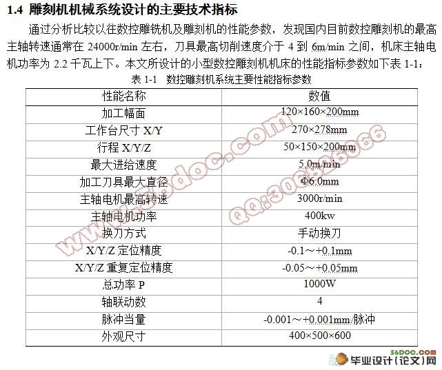
1.4 雕刻机机械系统设计的主要技术指标 4
2 雕刻机总体布局方案设计 5
2.1 数控雕刻机布局要求及影响因素 5
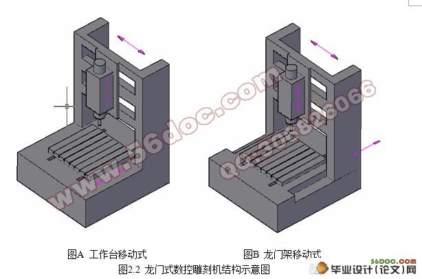
2.2 数控雕刻机总体结构布局 6
2.3 数控雕刻机结构的改良对比 7
2.4 工作台的结构设计 9
2.5 本章小结 10
3 主传动系统的方案设计 11
3.1 主运动传动系统设计 11
3.2 电主轴 12
3.2.1 电主轴的介绍 12
3.2.2 电主轴的结构及其优点 12
3.2.3 电主轴的安装 14
3.3 本章小结 14
4 机床进给系统方案设计 15
4.1 进给传动系统选择 15
4.1.1 进给传动系统的要求 15
4.1.2 进给传动系统的基本形式 15
4.1.3 以上几种传动方案的简介和比较 15
4.2 滚珠丝杠系统 17
4.2.1 滚珠丝杠副的选择 17
4.2.2 滚珠丝杠支承结构 17
4.2.3 支承轴承的选择 19
4.2.4 滚珠丝杠副的制动装置 19
4.2.5 步进电机与进给丝杠的联结结构 19
4.3 滚动导轨的安装定位 20
4.4 本章小结 20
5 主传动及X向进给系统部分零件计算和校核 21
5.1 主传动零部件计算及校核 21
5.1.1 主轴参数设计 21
5.1.2 主轴系统铣削力的计算 21
5.1.3 滚珠丝杠副参数的计算选择 22
5.1.4 滚珠丝杠副的强度校核 25
5.1.5 伺服电机参数计算和型号选择 26
5.2 X向进给系统零部件计算及校核 28
5.2.1 X向丝杠的选型及校核 28
5.2.2 丝杠轴承的选择及计算 29
5.3 本章小结 30
6 展望和结论 31
致 谢 32
参考文献 33
附 录 34
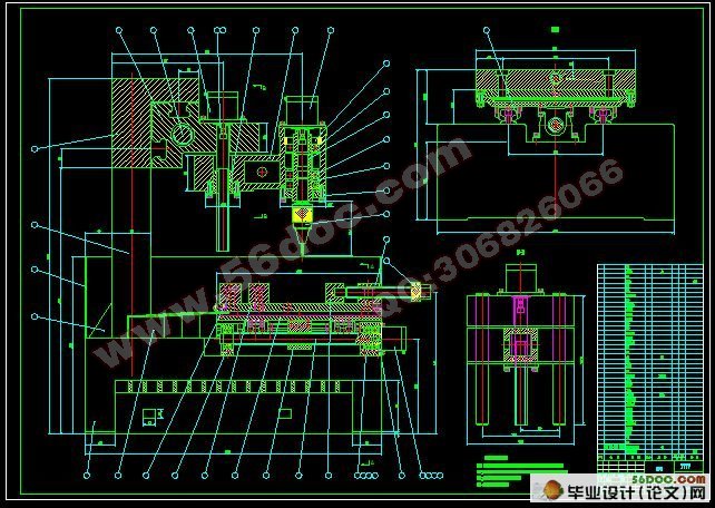
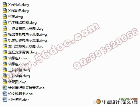
本次设计一共绘制图纸折合A0共3张,图纸信息如下表:
序号 图号 图纸名称 图符
1 DKJ-00 定梁式数控雕刻机装配图 A0
2 DKJ-00-01 轴承座1零件图 A2
3 DKJ-00-06 轴承座2零件图 A2
4 DKJ-00-03 丝杠支承滑块零件图 A3
5 DKJ-00-04 X向滑板零件图 A2
6 DKJ-00-16 衬套零件图 A4
7 DKJ-00-18 主轴轴套零件图 A4
8 DKJ-00-20 主轴端盖零件图 A4
9 DKJ-00-23 X向导轨零件图 A1
10 示意图1 电主轴结构图 A3
11 示意图2 横梁导轨布局示意图 A3
12 示意图3 工作平台结构示意图 A3
13 示意图4 机床初步布局示意图 A3
|
