流量为140t/h水-油浮头式换热器(含CAD零件装配图)(任务书,设计说明书10500字,CAD图纸8张)
摘 要
本设计说明书是关于浮头式换热器的设计,主要是进行了换热器的工艺计算、换热器的结构和强度设计。
换热器是化工、炼油、动力、食品、轻工、原子能、制药、机械及其其他许多工业部门广泛使用的一种通用设备。进二三十年来,化工、石油、轻工等过程工业得到了迅猛发展。因此,要求提供尺寸小,重量轻。换热能力大的换热设备。在设计过程中,我尽量采用较新的国家标准,做到既满足设计要求,又使结构优化,降低成本,以提高经济效益为主,力争使产品符合生产实际要求需要。适合市场激烈竞争。同时为了使本次设计能够进行顺利,我再设计前参阅了许多有关书籍和英文文献,并做了一定量的外文翻译工作。
已知条件为:设计压力为管程2.2MPa,壳程1.4MPa,工作温度管程1350℃,壳程95℃,设计温度管程112.5℃,壳程57.5℃,管程介质为油,壳程介质为水。依据给定条件,查GB151—1999书第138页,通过试算法获得总传热系数,所得传热面积为70.39m2。考虑到介质特性、其他因素,采用Φ25×2.5的不锈钢的无缝钢管作换热管,本设计采用300根换热管可满足换热量。设定拉杆数量为6,计算得到筒体直径为DN=700mm。完成了压降计算、管壁温度、传热系数计算等。强度设计中,依据GB150进行筒体、封头强度设计及校核,依据流量进行入口接管、出口接管等管口直径的选择,依据等面积补强法进行开口补强计算。本设计选择管板延长兼做法兰,依据GB151中的弹性支撑假设对管板进行设计和校核,管板与换热管的连接方式为焊接,拉杆与管板为螺纹连接结构。同时,进行了卧式容器鞍座校核。
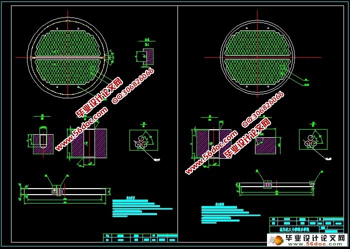
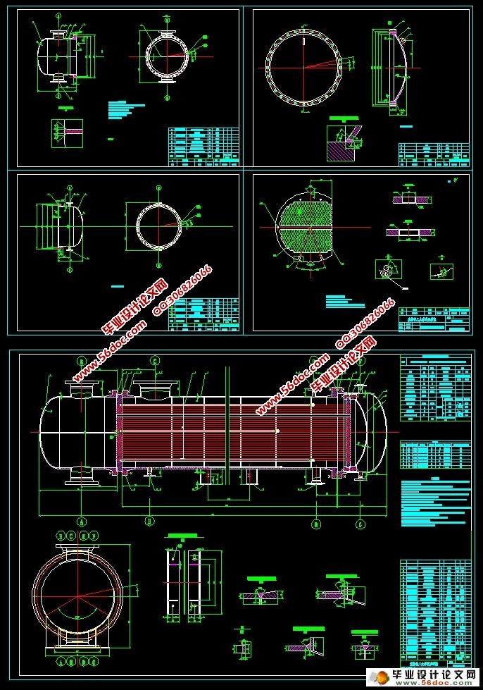
设计的前半部分主要是对换热器的原理、结构进行的详细的描述,从而进行换热器的选型,结构设计分析。设计的后半部分则是关于结构的强度的设计,主要是根据已经选定的换热器型式进行设备内各零部件的设计,如管板、折流板、定距管、钩圈、管厢等。包括:设计计算、材料的选择、具体尺寸确定、确定具体位置、管板厚度的计算、浮头盖和浮头法兰厚度的计算等。最后绘制一张装配图,三张零部件图。
关键词:浮头式换热器;设计;校核
Astract
The design specification is for the floating head heat exchanger design on, mainly for heat exchanger process calculation, design of the structure and intensity of the heat exchanger.
Heat exchangers are widely used in chemical, oil refining, power, food, light industry, atomic energy, pharmaceutical, machinery and many other industrial sectors. In the twenty or thirty years, chemical industry, petroleum, light industry and other process industries have been developing rapidly. Therefore, the requirement to provide a small size, light weight. Heat exchanging equipment for heat exchanging capacity. In the design process, I try to use a new national standard, do meets design requirements, also can make the structure optimization, reduce the cost, to improve the economic benefits, strive to make our products accord with the actual production requirements. Suitable for the fierce competition in the market. At the same time, in order to make this design can be carried out smoothly, I have to see a lot of books and English literature before the design, and do a certain amount of foreign language translation work.
Known conditions: the design pressure for the tube Cheng 2.2MPa, shell 1.4MPa, the operating temperature of 1350 degrees Celsius, shell 95 degrees Celsius, the design temperature of 112.5 degrees Celsius, shell 57.5 degrees, the tube is oil, the shell side of the medium for water. According to the given conditions, the GB151 - 1999 book 138th pages, the total heat transfer coefficient was obtained by trial calculation method, the heat transfer area was 70.39m2. Considering the medium characteristics and other factors, the phi 25 x 2.5 stainless steel seamless steel tube as heat transfer tube. The design uses 300 tube can meet the heat transfer. The number of the set rod is 6, and the diameter of the cylinder is DN=700mm. The calculation of the pressure drop, the wall temperature and heat transfer coefficient were completed. In the strength design and GB150 basis for cylinder head design and strength check, according to the flow of inlet takeover, outlet nozzle and orifice diameter selection, on the basis of the area fill method to an opening reinforcement calculation. The design selection of pipe plate to extend and do the flange, based on the elastic support GB151 assumption on the tube plate design and check, tube plate and heat exchanger tube connection for welding, tie rod and tube plate for the threaded connection structure. At the same time, the horizontal vessel saddle check.
The design part is mainly detailed description of the principle and the structure of the heat exchanger, so as to change the selection of heat exchanger, structural design and analysis. The latter part of the design is about the strength of the structure design, mainly is according to the already selected for heat exchanger type design of equipment parts, such as the tube plate, baffle, spacer tube, circle hook, tube car. Including: the design and calculation, material selection, identify specific size, determine specific location, calculation of tube plate thickness, the floating head cover and floating head flange thickness calculation. At last, draw an assembly drawing and three parts.
Keywords: Floating head heat exchanger; Design; Check
目 录
第一章 综述 1
引言 1
1.1换热器按作用原理或传热方式分类 1
1.1.1直接接触式换热器 1
1.1.2蓄热式换热器 1
1.1.3间壁式换热器 1
1.1.4中间载热式换热器 2
1.2管壳式换热器的分类 2
1.2.1固定管板式换热器 2
1.2.2浮头式换热器 2
1.2.3 U形管换热器 3
1.2.4填料函式换热器 3
1.2.5换热器的制造 3
1.3 结语 4
参考文献 5
第二章 传热工艺计算 6
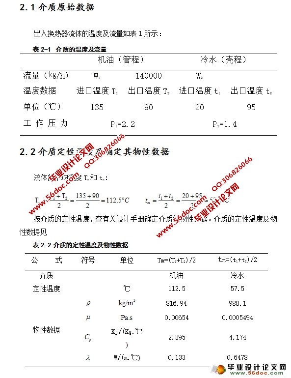
2.1介质原始数据 6
2.2介质定性温度及确定其物性数据 6
2.3有效平均温差计算 7
2.4传热量及物料衡算 7
2.5管程结构初步设计 8
2.6壳程换热系数计算 9
2.7传热系数计算 9
2.8管壁温度计算 10
2.9管程压降计算 10
2.10壳程压降计算 11
第三章 结构设计及强度运算 12
3.1换热管材料及规格的选择和根数的确定 12
3.2布管方式的选择 12
3.3筒体内径的确定 13
3.4筒体壁厚的确定 14
3.5筒体水压试验 15
3.6管箱侧封头厚度的确定 15
3.7浮头侧封头厚度的确定 17
3.8设备法兰的选择 18
3.10浮头侧法兰的选择 18
3.11接管法兰的选择 19
3.12浮头换热器固定管板的设计计算 20
3.13浮头设计计算 22
3.14管程压力(内压)作用下浮头盖的计算 23
3.15壳程压力(外压)作用下浮头盖的计算 23
3.16管程压力作用下浮头法兰的计算 24
3.17壳程压力作用下浮头法兰的计算 26
3.18钩圈的选择: 28
3.19浮动管板的选择: 28
3.20折流板的选择 29
3.21管箱短节壁厚计算 29
3.21.1壳程短节 29
3.21.2管程短节 29
3.22防冲板的选择 30
3.23接管及开孔补强 30
3.24支座的选择 31
3.24.1管程短节 32
3.24.2切向切应力校核 33
3.24.3周向应力校核 33
3.24.4鞍座腹板应力 33
参考文献 34
致谢 35
|