叉形件工艺及铣床夹具设计(任务书,开题报告,外文翻译,设计说明书12600字,cad图纸3张,答辩PPT,工艺规程)
摘 要
本次毕业设计的题目是叉形件加工工艺及夹具设计。叉形件是飞机液压助力器执行机构中的主要部件之一,在产品的某组件中内孔Φ10和外圆Φ9与叉形件组件中的外圆和内孔配合,起到一个连接的作用。
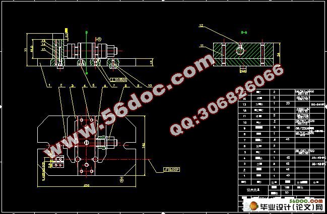
主要的设计思路是:分析零件特点及拟订合理的工艺规程,依据工艺规程设计,选择机床和设计合理的夹具。在机械加工中如果能广泛地使用夹具,就能极大的节省加工时的辅助时间,以减轻工人的劳动量,提高产品的质量和劳动生产率。 设计夹具一般先对原始材料进行分析,明确设计要求和意图,然后提出具体的定位、夹紧、对刀方案和夹具体的一般结构。本文采用六点定位的定位方法,夹紧螺钉与双向压板组合的夹紧方法,为保证设计的可靠性,还对夹具的精度进行了分析。
本次毕业设计是专业课程的理论学习和实践之后的最后一个教学环节,通过本次设计对所学专业课程的理论加以综合并增加生产实践知识,经过实际训练,从而培养和提高个人独立工作的能力。巩固与扩充了相关课程内容,掌握其设计的方法和步骤。在设计中查阅了大量的机械书籍,在此过程中锻炼并提高了机械设计的基本技能,如计算、绘图、查阅设计资料和手册;熟悉机械设计标准及其它有关的标准和规范,并在设计中加以贯彻,对今后的工作与学习打下了坚实的基础。
关键词:叉形件,工艺规程,机床夹具
ABSTRACT
This graduation design topic is Y-piece processing and milling fixture design. Y-piece is one of the main components of aircraft hydraulic actuators in the booster, a component within the product and cylindrical hole Φ10 Φ9 and Y-piece assembly with the outer and inner hole, played the role of a connection .
The main design way of thinking BE: the feature of the parts is analyzed so as to plan the reasonable process and select the corresponding machine and jig. Machined parts if they can widely used fixture, you can greatly save the auxiliary time when the processing in order to reduce the amount of labor of workers, improve product quality and labor productivity. Design fixture first general analysis of the raw materials, design requirements and intentions clear, and then propose specific positioning, clamping programs and folders specific general structure of the knife. In this paper, six o'clock positioning, clamping the clamping bolts and two-way plate combination in order to ensure the reliability of the design, but also on the accuracy of the fixture.
This graduation design is profession course of theories study and after practice of the last teaching link, pass this design to learn profession course of the theories take in to synthesize and increase produce to practice knowledge, pass by training of machine design, develop and raise thus personal independence work of ability. Make stronger and enlarged the related course contents. Control the method and step of its design. Checked a great deal of machine book in the design, toughen in this process and raised the basic technical ability of machine design, such as calculation, paint, check design data and manual; Acquaint with standard and other of the machine design relevant of standard and norm, and take in to carry through in the design, to aftertime's work and study beat under solid foundation.
KEY WORDS: Y-piece , Process planning, Machine tool fixtures
1.1.零件的作用
叉形件零件是飞机液压助力器执行机构中的主要部件之一。从整体上来看,飞机液压助力器是安装在飞机副翼操纵机构中或方向舵操纵系统中,用于不可逆的液压助力器操纵。当飞机液压系统损坏或压力下降时,液压助力器外筒左右两腔沟通,即助力器当一拉杆使用,以实现人力应急操纵。每架飞机上装有两台液压助力器。分别操纵左右副翼或方向舵。
叉形件零件在产品中内孔φ10H7和外圆φ9h6与叉形件组件中的外圆和内孔配合,起到一个连接的作用。
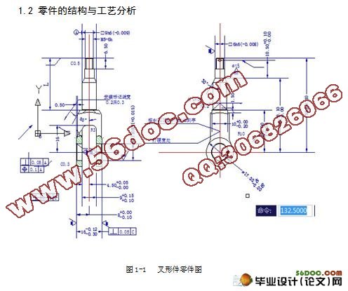
1.2 零件的结构与工艺分析
从叉形件的结构特征来看(见上图1-1),它是长度大于直径的回转体零件,其被加工表面有外圆柱面、外圆锥面、螺纹、沟槽、孔等。根据它的结构特点和精度要求,应选择合理的定位基准和加工方法。
叉形件的技术要求是根据零件的主要功用以及使用条件确定的,通常有以下几个方面:
(1)加工精度。叉形件的加工精度主要包括结构要素的尺寸精度、形状精度和位置精度。
1)尺寸精度。主要指结构要素的直径和长度的精度。
2)形状精度。主要指轴颈的圆度、圆柱度等,因轴的形状误差直接影响与之配合的零件接触质量和回转精度,因此限制在直径公差范围内。
3)位置精度。包括两叉内、外端对表面C的垂直度,孔对表面A的垂直度及位置度要求,具体参阅零件图。
(2)表面粗糙度。轴类零件的主要工作表面粗糙度根据其运转速度和尺寸精度等级决定。本零件中主要表面的表面粗糙度Ra为1.6~0.4,次要表面的表面粗糙度Ra为12.5~3.2。
(3)其他要求。为改善轴类零件的切削加工性能或提高综合力学性能及其使用寿命等,还必须根据轴的材料和使用条件,规定相应的热处理要求。
设计基准是φ9的中心线;配合表面是外圆φ9,内孔φ10,叉形件在装配过程中,内孔φ10H7 和外圆φ9h6在叉形组件中是配合表面,因此配合部分的尺寸公差、形位公差要求比较高,表面粗糙度要求较高,外圆φ10H7是设计基准表面;M5-6h螺纹上有一个φ1.5的小孔起漏气漏油作用,因此这部分的精度要求不高;
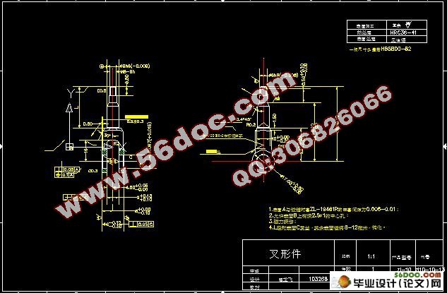
主要技术要求:
1.表面A的中心线对内孔φ10H7轴线的垂直度公差为0.05,位置度公差不大于0.1;
2.槽与外形的轴线对内孔φ10H7的内壁的垂直度公差都为0.05;
3.表面A与铰链衬套ZL-19461R的配套间隙为0.006-0.01;
4.允许表面B上有孔深2.5, φ1的中心孔;
5.磁力探伤;
6.L段和表面C发兰,其余表面镀镉8-12μ,钝化;
7,叉形件从构形来看,基本属于轴类件,各个表面并不复杂。叉形件从精度上看,主要工作表面的精度是IT6级,孔φ10H7工作表面的粗糙度为0.8,非配合表面的粗糙度为1.6-3.2,位置精度:φ10H7的孔中心线对A的位置度为0.1,垂直度公差为0.05;
目录
前 言 - 1 -
第一章 零件的分析 - 2 -
1.1零件的作用 - 2 -
1.2 零件的结构与工艺分析 - 2 -
第二章 工艺规程设计 - 4 -
2.1确定毛坯的制造形式 - 4 -
2.2 基准的选择 - 4 -
2.2.1粗基准的选择 - 4 -
2.2.2精基准的选择 - 4 -
2.3加工阶段的划分 - 5 -
2.3.1零件加工阶段的划分 - 5 -
2.3.2.工序的集中与分散 - 5 -
2.4.制定工艺路线及方案 - 5 -
2.5 机械加工余量、工序尺寸的确定 - 7 -
2.6尺寸链的计算 - 7 -
第三章 铣床夹具设计 - 9 -
3.1装夹方案的确定 - 10 -
3.1.1定位基准的选择 - 10 -
3.1.2装夹方案 - 10 -
3.2夹具设计及解析 - 11 -
3.2.1.夹具精度分析 - 12 -
3.2.2.夹具设计及操作的简要说明 - 14 -
参考文献 - 15 -
致 谢 - 16 -
毕业设计小结 - 17 -
附 录 - 18 -
|