«ѓњйЉ”є§є§“’Љ∞„®”√Љ–Њя…иЉ∆(CAD,SolidWorks»эќђ)(»ќќс й,њ™ћв±®Єж,ЌвќƒЈ≠“л,љшґ»Љ∆їЃ±н,¬џќƒЋµ√ч й13000„÷,cadЌЉ÷љ11’≈) °°°°
’™ “™
“«ѓњйЉ”є§є§“’Љ∞„®”√Љ–Њя…иЉ∆”’вЄцћвƒњєЋ√ыЋЉ“е£ђЈ÷ќ™ЅљЄц≤њЈ÷£ђ“їЄц «’лґ‘їоґѓ«ѓњйµƒЉ”є§є§“’£ђЅн“їЈљ√жЊЌ «’лґ‘’вЄц≥яізµƒ«ѓњй…иЉ∆≥ц“їЄц„®√≈µƒЉ–Њя£ђ’в“™«уќ“√«ЋƒƒкЋщ—І÷™ ґµƒЉѓ÷–”¶”√°£
‘Џ’вЄц…иЉ∆÷–£ђ „ѕ»√ч∞„«ѓњй « ≤√і£њ”– ≤√і„ч”√£њќ™іЋ£ђќ“„®√≈„цЅЋЅгЉюЈ÷ќц£ђЋьµƒћЎµг£ђ“™«у£ђ–и“™Љ”є§µƒµЎЈљ£ђ“‘Љ∞ЉЉ х“™«уµ»µ»£ђ‘ЏЉ”є§≤ƒЅѕЈљ√жќ“—°‘сЅЋї“њЏ÷эћъ£ђ“тќ™ЋьµƒЅ¶—І–‘ƒ№Ї√£ђЉџЄс≤їЄя£ђ«“»Ё“„їсµ√£ђќ“ЄщЊЁƒњ±кЅгЉюµƒ≥яіз£ђќ“÷∆ґ©ЅЋ74×64×32µƒ√Ђ≈ч£ђ‘ўљбЇѕїщ√жѕ»––£ђѕ»і÷ЇуЊЂ£ђѕ»÷чЇуіќ£ђѕ»√жЇуњ„µƒ‘≠‘т“≤ќ™ЅЋЉх…ў„∞–ґіќ э÷∆ґ©ЅЋ»зѕ¬Љ”є§є§“’єэ≥ћ£Ї
÷э‘м—— µ–І——Ќњµ„∆б——і÷ѕ≥…ѕ±н√ж——і÷ѕ≥ѕ¬±н√ж——і÷ѕ≥„уґЋ√ж——„кφ20µƒњ„—— „кM10¬Ёќ∆њ„µƒµ„њ„——∞лЊЂѕ≥ѕ¬±н√ж—— ј©φ20H8µƒњ„—— ј©φ28µƒњ„£ї——љ¬φ20H8µƒњ„——є•M10µƒ¬Ёќ∆
‘Џ’ыЄцЉ”є§є§“’÷–£ђ√жµƒЉ”є§ќ“—°‘сXA6132ѕ≥і≤£ђґ‘”Џњ„µƒЉ”є§ќ“—°‘сЅЋZ3040„кі≤£ђґ‘µґЊяµƒ—°‘с£ђ÷ч÷б„™Ћў£ђљшЄшЋўґ»£ђ±≥≥‘µґЅњ∞і’’„‘ЉЇµƒЋЉ¬Ј£ђ÷р“ї„цЅЋЅ–ЊўЉ∆Ћг£ђѕкѕЄ«лњіє§“’Ј÷ќцєэ≥ћЇЌє§“’њ®∆ђ°£
ґ‘”ЏЉ–Њяµƒ…иЉ∆£ђ”¶µ±¬ъ„гЉ”є§є§Љюƒ№єїЈљ±гЉ–≥÷£ђƒ№єї¬ъ„гє§Љюµƒіуєжƒ£…ъ≤ъ£ђ«“љбєє≤їћЂЄі‘”£ђљбЇѕЉ”є§є§“’ґ‘∆д„цЇ√Љ–љфЅ¶µƒЉ∆Ћг£ђЅ¶—І–£ЇЋ£ђЇЌґ®ќїЈ÷ќцµƒїщі°…ѕ…иЉ∆Љ–Њя£ђї≠≥цѕа”¶µƒґюќђ»эќђЌЉ£ђ’ыјнЇ√Їу«лјѕ ¶≤й‘ƒ°£Ћ≥јыЌк≥…±ѕ“µір±з°£
єЎЉь„÷£Ї є§“’£їЉ–Њя£їЉ∆Ћг£їЈ÷ќц
Abstract
"This topic clamp block processing technology and special fixture design" as the name implies, is divided into two parts, one is the process of active clamp block, on the other hand is the size of the clamp block to design a special fixture, focused on the application of the requirements of our four years of knowledge.
In this design, first understand clamp block is what? What effect is there? Therefore, I made the analysis of requirements of parts, its characteristics, needs, processing areas, as well as the technical requirements and so on, in the process I chose the materials of cast iron, because of its good mechanical performance, the price is not high, and easy to get, I according to the target part size, I made 74 * 64 * 32 blank, combined with the base first, coarse to fine, after the first primary time, the surface after the first hole principle in order to reduce the loading and unloading times for the following process:
Casting -- effectiveness -- primer -- rough milling surface -- rough milling surface -- rough milling left end -- hole drilling drill φ 20 -- M10 threaded hole bottom -- half precision milling surface -- expansion of φ 20H8 φ 28 hole -- expanding holes; threads -- hinge hole and φ 20H8 -- M10
In the whole process, the machining I choose XA6132 milling machine for the machining of the hole, I chose the Z3040 drilling machine, the feed rate of the cutting tool choice, spindle speed, depth of cut, according to their own ideas, one by one to do lists calculation, see the process analysis and process card.
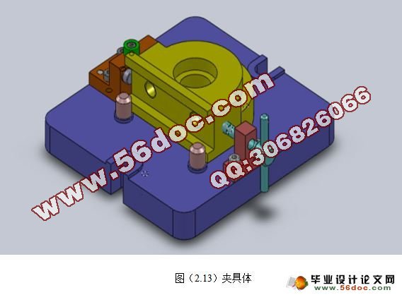
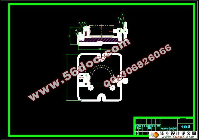
Fixture for the design, should meet the workpiece can be conveniently clamped, can satisfy the large-scale production of the workpiece, and the structure is not too complex, calculation, do clamping force on the binding process of mechanics analysis, and based on the analysis of fixture locating design, draw the 2D and 3D graph corresponding, good after finishing please refer to. Successfully completed the graduation reply.
Key words: technology; fixture; calculation; analysis
ЅгЉюµƒє§“’–‘Ј÷ќцЇЌЅгЉюЌЉµƒ…у≤й
Є√ЅгЉюЌЉµƒ ”ЌЉ’э»Ј£ђЌк’ы£ђ≥яіз£ђєЂ≤оЉ∞ЉЉ хґЉЈыЇѕ“™«у°£µЂ «ЅгЉюµƒЉ”є§єэ≥ћ“™«уЊя”–љѕЄяµƒ±н√жі÷≤Џґ»£ђЄч„∞≈дїщ√жµƒљбєє“™«у”–“їґ®µƒ≥яізЊЂґ»ЇЌ∆љ––ґ»°£Јс‘тїб”∞ѕмїъ∆чµƒ…и±Є–‘ƒ№ЇЌ„∞≈дЊЂґ»°£Ћд»їЅгЉюµƒљбєє≤ї «ћЂљѕЄі‘”£ђµЂќ™ЅЋћбЄяЉ”є§–І¬ £ђ‘ЏЉ”є§ ±“™≤…”√„®”√µƒЉ–Њяљш––„∞Љ–ґ®
ЅгЉюµƒ„ч”√
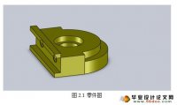
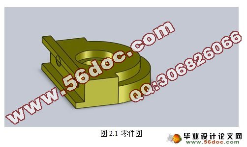
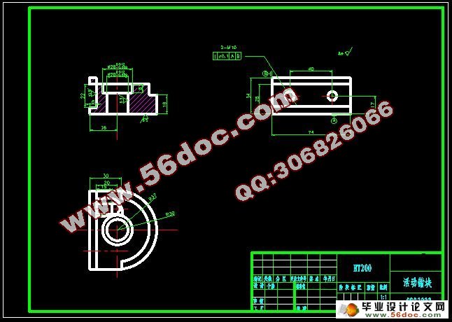
ћвƒњЄш≥цµƒЅгЉюїоґѓ ««ѓњй£®ЌЉ2.1£©°£Ћьµƒ÷ч“™µƒ„ч”√ «”√„чќ™“їЄц∆’Ќ®ЅгЉю£ђ‘Џїъ–µЄч––“µґЉ±Ў≤їњ……ў£ђ∆р÷І≥≈£ђєћґ®µ»„ч”√°£
2.1.3 ЅгЉюµƒє§“’Ј÷ќц
»зЌЉ1-1Ћщ Њ£ђЅгЉюЄь Їѕ є”√ѕ≥Љ”є§£ђљбєєЉтµ•£ђ–иЉ”є§µƒ±н√ж”–£Ї
£®1£©ЅгЉюµƒ…ѕѕ¬∆љ√ж£ђ≥§74mm£ђЄя28mmѕ¬ґЋ√жі÷≤Џґ»Ra6.3£ї
£®2£©…ѕґЋ√жѕтѕ¬÷Ѕ22mmі¶µƒћ®љ„£ђ±£÷§і÷≤Џґ»Ra12.5£ї
£®3£©…ѕґЋ√жØ28ЇЌØ20H8µƒЅљЄц÷––ƒњ„£ђі÷≤Џґ»±£÷§Ra6.3£ї
£®4£©Ѕљі¶¬Ёќ∆њ„,2-M10£ї
2.2 є§“’Ј÷ќцЉ∞…ъ≤ъја–Ќµƒ»Јґ®
2.2.1 »Јґ®√Ђ≈ч÷∆‘м–ќ љ
ЅгЉюµƒ≤ƒЅѕHT200°£њЉ¬«µљЅгЉю‘Џє§„ч÷–і¶”Џ»уїђ„іћђ£ђ≤…”√»уїђ–ІєыљѕЇ√µƒ÷эћъ°£”…”Џƒк≤ъЅњіпµљ÷–≈ъ…ъ≤ъµƒЋЃ∆љ£ђґш«“ЅгЉюµƒ¬÷ј™≥яіз≤їіу£ђ÷э‘м±н√ж÷ Ѕњµƒ“™«уЄя£ђє њ…≤…”√÷э‘м÷ Ѕњќ»ґ®µƒ£ђ Їѕіу≈ъ…ъ≤ъµƒљр фƒ£÷э‘м°£”÷”…”ЏЅгЉюµƒґ‘≥∆ћЎ–‘£ђє ≤…»°ЅљЉю÷э‘м‘Џ“ї∆рµƒЈљЈ®£ђ±г”Џ÷э‘мЇЌЉ”є§є§“’єэ≥ћ£ђґш«“їєњ…“‘ћбЄя…ъ≤ъ¬ °£
ЄщЊЁ÷э‘мµƒ÷э‘мЉю≥яізµƒіу–°ЇЌ–ќ„і£ђ«“—°”√ї“÷эћъќ™≤ƒЅѕ£ђ≤Ґ«“÷эЉюµƒ±н√жЊЂґ»“™«у≤ї «ћЂЄя£ђљбЇѕ…ъ≤ъ–І¬ ЇЌћхЉюњ…—°”√…∞–Ќ÷э‘м
ƒњ ¬Љ
1 –ч¬џ 1
1.1 ±Њњќћв—–ЊњµƒƒЏ»ЁЇЌ“в“е 1
1.2 єъƒЏЌвµƒЈҐ’єЄ≈њц 1
1.3 ±Њњќћв”¶іпµљµƒ“™«у 1
2 …иЉ∆ƒЏ»Ё 2
2.1 ЅгЉюЈ÷ќц 2
2.1.1 ЅгЉюµƒє§“’–‘Ј÷ќцЇЌЅгЉюЌЉµƒ…у≤й 2
2.1.2 ЅгЉюµƒ„ч”√ 3
2.1.3 ЅгЉюµƒє§“’Ј÷ќц 3
2.2 є§“’Ј÷ќцЉ∞…ъ≤ъја–Ќµƒ»Јґ® 3
2.2.1 »Јґ®√Ђ≈ч÷∆‘м–ќ љ 3
2.2.2 є§“’єж≥ћµƒ„ч”√ 4
2.2.3 їщ√жµƒ—°‘с 4
2.2.4 є§Љю±н√жЉ”є§ЈљЈ®µƒ—°‘с 4
2.2.7 »Јґ®«–ѕч”√ЅњЉ∞їщ±Њє§ ± 10
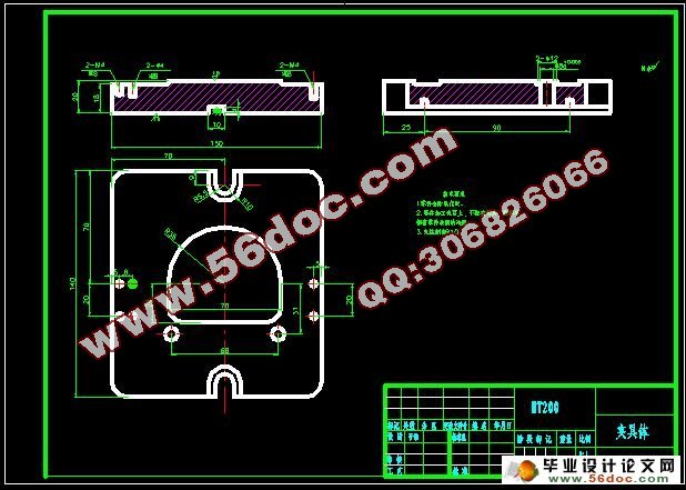
2.3 Љ–Њя…иЉ∆ 23
2.3.1 ќ ћвµƒћб≥ц 23
2.3.2 ґ®ќїїщ„Љµƒ—°‘с 23
2.3.4 «–ѕчЅ¶Љ∞Љ–љфЅ¶Љ∆Ћг 25
2.3.6 Љ–Њя…иЉ∆Љ∞≤ў„чЉт“™Ћµ√ч 27
÷¬–ї 28
≤ќњЉќƒѕ„ 29
Єљ¬Љ 30
|