左摆动杠杆工艺规程及钻Ф12孔的夹具设计(课程设计)(说明书4800字,工艺卡,CAD图4张)
摘 要
本次设计内容涉及了机械制造工艺及机床夹具设计、金属切削机床、公差配合与测量等多方面的知识。
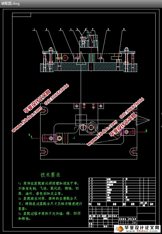
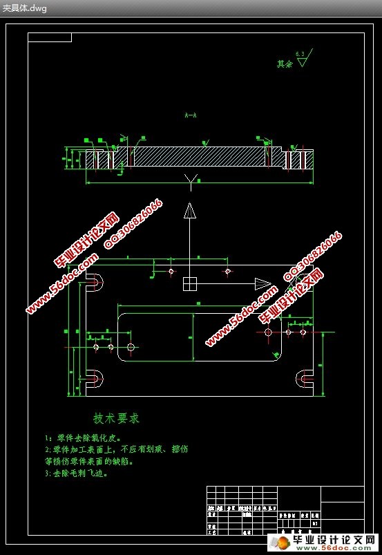
左摆动杠杆加工工艺规程及其钻Φ12孔的夹具设计是包括零件加工的工艺设计、工序设计以及专用夹具的设计三部分。在工艺设计中要首先对零件进行分析,了解零件的工艺再设计出毛坯的结构,并选择好零件的加工基准,设计出零件的工艺路线;接着对零件各个工步的工序进行尺寸计算,关键是决定出各个工序的工艺装备及切削用量;然后进行专用夹具的设计,选择设计出夹具的各个组成部件,如定位元件、夹紧元件、引导元件、夹具体与机床的连接部件以及其它部件;计算出夹具定位时产生的定位误差,分析夹具结构的合理性与不足之处,并在以后设计中注意改进。
关键词:工艺、工序、切削用量、夹紧、定位、误差。
ABSTRCT
This design content has involved the machine manufacture craft and the engine bed jig design, the metal-cutting machine tool, the common difference coordination and the survey and so on the various knowledge.
The reduction gear box body components technological process and its the processing ¢ 140 hole jig design is includes the components processing the technological design, the working procedure design as well as the unit clamp design three parts. Must first carry on the analysis in the technological design to the components, understood the components the craft redesigns the semi finished materials the structure, and chooses the good components the processing datum, designs the components the craft route; After that is carrying on the size computation to a components each labor step of working procedure, the key is decides each working procedure the craft equipment and the cutting specifications; Then carries on the unit clamp the design, the choice designs the jig each composition part, like locates the part, clamps the part, guides the part, to clamp concrete and the engine bed connection part as well as other parts; Position error which calculates the jig locates when produces, analyzes the jig structure the rationality and the deficiency, and will design in later pays attention to the improvement.
Keywords: The craft, the working procedure, the cutting specifications, clamp, the localization, the error
1.1:零件的作用
左摆动杠杆的作用待查
1.2、零件的工艺分析
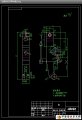
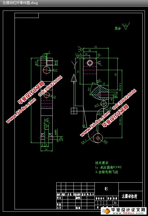
左摆动杠杆的加工共有3组加工表面,它们相互之间有一定的要求。现分述如下:
1、以工件的左端面为基准加工右端面。
2、以有端面为基准加工M10底孔,直径为12的通孔,直径为6的通孔。
3:以一端面和M10底孔和直径为6的通孔为基准加工上端面和左右2端面。铣2mm槽,铣8mm槽
有以上的分析可知,对于这两组加工表面而言,可以先加工其中一组表面,然后借助于夹具加工另一组表面,并保证它们的精度。
目 录
序言…………………………………………………………………1
一. 零件分析 ……………………………………………………2
1.1 零件作用 ………………………………………………2
1.2零件的工艺分析 …………………………………………2
二. 工艺规程设计…………………………………………………3
2.1确定毛坯的制造形式 ……………………………………3
2.2基面的选择传 ……………………………………………4
2.3制定工艺路线 ……………………………………………4
2.4机械加工余量、工序尺寸及毛坯尺寸的确定 …………7
2.5确定切削用量及基本工时………………………………13
三 夹具设计……………………………………………………14
3.1问题的提出………………………………………………14
3.2定位基准的选择…………………………………………14
3.3定位元件的设计…………………………………………14
3.4切削力及夹紧力计算……………………………………15
3.5定位误差分析……………………………………………15
3.6夹具设计及操作简要说明………………………………16
总 结………………………………………………………………20
致 谢………………………………………………………………21
参考文献 …………………………………………………………22
|