变速箱箱体加工工艺与夹具设计
来源:56doc.com 资料编号:5D11531 资料等级:★★★★★ %E8%B5%84%E6%96%99%E7%BC%96%E5%8F%B7%EF%BC%9A5D11531
资料以网页介绍的为准,下载后不会有水印.资料仅供学习参考之用. 密 保 惠 帮助
资料介绍
变速箱箱体加工工艺与夹具设计(选题审题表,任务书,中期检查表,论文说明书19000字,工艺卡,CAD图纸5张)
摘 要
本设计是变速箱箱体零件的加工工艺规程及一些工序的专用夹具设计。变速箱箱体零件的主要加工表面是平面及孔系。一般来说,保证平面的加工精度要比保证孔系的加工精度容易。因此,本设计遵循先面后孔的原则。并将孔与平面的加工明确划分成粗加工和精加工阶段以保证孔系加工精度。基准选择以变速箱箱体的输入轴和输出轴的支承孔作为粗基准,以顶面与两个工艺孔作为精基准。主要加工工序安排是先以支承孔系定位加工出顶平面,再以顶平面与支承孔系定位加工出工艺孔。在后续工序中除个别工序外均用顶平面和工艺孔定位加工其他孔系与平面。支承孔系的加工采用的是坐标法镗孔。整个加工过程均选用组合机床。夹具选用专用夹具,夹紧方式多选用气动夹紧,夹紧可靠,机构可以不必自锁。因此生产效率较高。适用于大批量、流水线上加工。能够满足设计要求。
关键词:变速箱 加工工艺 专用夹具
ABSTRACT
The design is about the special-purpose clamping apparatus of the machining technology process and some working procedures of the gearbox parts. The main machining surface of the gearbox parts is the plane and a series of hole. Generally speaking, to guarantee the working accuracy of the plane is easier than to guarantee the hole’s. So the design follows the principle of plane first and hole second. And in order to guarantee the working accuracy of the series of hole, the machining of the hole and the plane is clearly divided into rough machining stage and finish machining stage. The supporting hole of the input bearing and output bearing is as the rough datum. And the top area and two technological holes are as the finish datum. The main process of machining technology is that first, the series of supporting hole fix and machine the top plane, and then the top plane and the series of supporting hole fix and machine technological hole. In the follow-up working procedure, all working procedures except several special ones fix and machine other series of hole and plane by using the top plane and technological hole. The machining way of the series of supporting hole is to bore hole by coordinate. The combination machine tool and special-purpose clamping apparatus are used in the whole machining process. The clamping way is to clamp by pneumatic and is very helpful. The instruction does not have to lock by itself. So the product efficiency is high. It is applicable for mass working and machining in assembly line. It can meet the design requirements.
Key Words:Gearbox machining technology special-purpose clamping apparatus
1.1零件的分析
1.1.1零件的作用
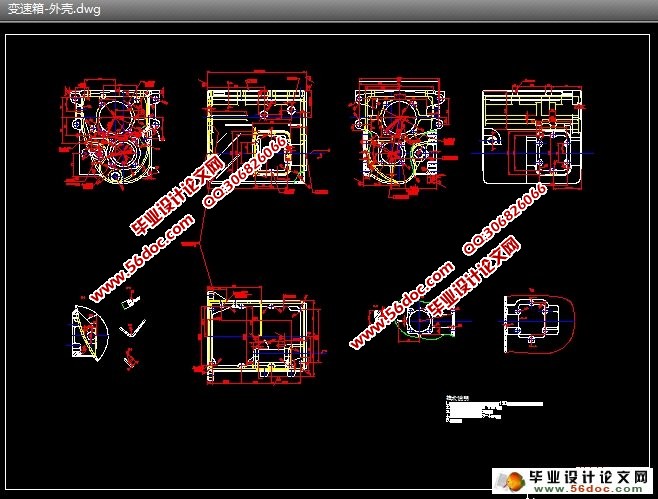
题目给出的零件是变速箱箱体。变速箱箱体的主要作用是支承各传动轴,保证各轴之间的中心距及平行度,并保证变速箱部件与发动机正确安装。因此变速箱箱体零件的加工质量,直接影响变速箱的装配精度和运动精度,使用性能和寿命。变速箱主要是实现速度的改变。变速箱箱体零件的顶面用以安装变速箱盖,前后端面支承孔 、 用以安装传动轴,实现其变速功能。
1.1.2零件的工艺分析
由变速箱箱体零件图可知。变速箱箱体是一个簿壁壳体零件,它的外表面上有五个平面需要进行加工。支承孔系在前后端面上。此外各表面上还需加工一系列螺纹孔。因此可将其分为三组加工表面。它们相互间有一定的位置要求。现分析如下:
1、以顶面为主要加工表面的加工面。这一组加工表面包括:顶面的铣削加工; 的螺孔加工; 的工艺孔加工。其中顶面有表面粗糙度要求为 ,8个螺孔均有位置度要求为 ,2个工艺孔也有位置度要求为 。
2、以 、 、 的支承孔为主要加工表面的加工面。这一组加工表面包括:2个 、2个 和1个 的孔;尺寸为 的与 、 的4个孔轴线相垂直的前后端面;前后端面上的3个 、16个 的螺孔,以及4个 、2个 的孔;还有另外两个在同一中心线上与两端面相垂直的 的倒车齿轮轴孔及其内端面和两个 的螺孔。其中前后端面有表面粗糙度要求为 ,3个 、16个 的螺孔,4个 、2个 的孔均有位置度要求为 ,两倒车齿轮轴孔内端面有尺寸要求为 及表面粗糙度要求为 。
3、以两侧窗口面为主要加工平面的加工面。这一组加工表面包括:尺寸为 和 的两侧窗口面;与两侧窗口面相垂直的12个 的螺孔;与两侧面成 角的尺寸为 的锥管螺纹孔(加油孔)。其中两侧窗口面有表面粗糙度要求为 ,12个螺孔均有位置度要求为 。
目 录
摘要……………………………………… ……… ……… ……… ……………..…. . .I
绪论…………………………………………………… …… …… .….………………. 1
第1章 变速箱箱体加工工艺规程设计 …………………… …… .….… ………… 2
1.1 零件的分析………………………………………………………………………2
1.1.1零件的作用…………………………………………………………………2
1.1.2零件的工艺分析……………………………………………………………2
1.2变速箱箱体加工的主要问题和工艺过程设计所应采取的相应措施 ……3
1.2.1孔和平面的加工顺序………………………………………………………3
1.2.2孔系加工方案选择…………………………………………………………3
1.3变速箱箱体加工定位基准的选择……………………………………………5
1.3.1粗基准的选择………………………………………………………………5
1.3.2精基准的选择………………………………………………………………6
1.4变速箱箱体加工主要工序安排………………………………………………6
1.5机械加工余量、工序尺寸及毛坯尺寸的确定………………………………8
1.6确定切削用量及基本工时(机动时间)……………………………………13
1.7时间定额计算及生产安排……………………………… ……… …… …………32
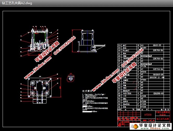
第2章 专用夹具设计 ………………………………………………………………39
2.1加工工艺孔夹具设计……………………………………………………………39
2.1.1定位基准的选择……………………………………………………………39
2.1.2切削力的计算与夹紧力分析……………………………………………39
2.1.3夹紧元件及动力装置确定………………………………………………40
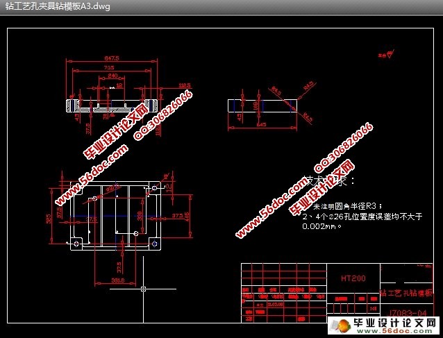
2.1.4钻套、衬套、钻模板及夹具体设计………………………………………41
2.1.5夹具精度分析……………………………………………………………43
2.1.6夹具设计及操作的简要说明……………………………………………44
2.2粗铣前后端面夹具设计……………………………………………………45
2.2.1定位基准的选择…………………………………………………………45
2.2.2定位元件的设计…………………………………………………………45
2.2.3定位误差分析……………………………………………………………47
2.2.4铣削力与夹紧力计算……………………………………………………47
2.2.5定向键与对刀装置设计…………………………………………………48
2.2.6夹紧装置及夹具体设计…………………………………………………49
2.2.7夹具设计及操作的简要说明………………………………… ……………… 51
结论…………………………………………………………… …………………… 53
致谢……………………………….……………………..… ……… ……...… ……... 54
参考文献………………………….…………… ……..……..…… ……… ….……... 55
|