发动机曲轴箱工艺孔钻床夹具设计(含CAD零件图装配图)
来源:56doc.com 资料编号:5D11811 资料等级:★★★★★ %E8%B5%84%E6%96%99%E7%BC%96%E5%8F%B7%EF%BC%9A5D11811
资料以网页介绍的为准,下载后不会有水印.资料仅供学习参考之用. 密 保 惠 帮助
资料介绍
发动机曲轴箱工艺孔钻床夹具设计(含CAD零件图装配图)(论文说明书16000字,CAD图32张)
摘 要:机床夹具是由定位元件,夹紧装置,对刀元件,夹具体部分组成,机床夹具设计也就是针对夹具组成的各个部分进行设计。
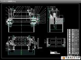
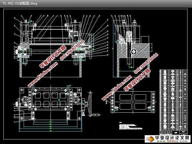
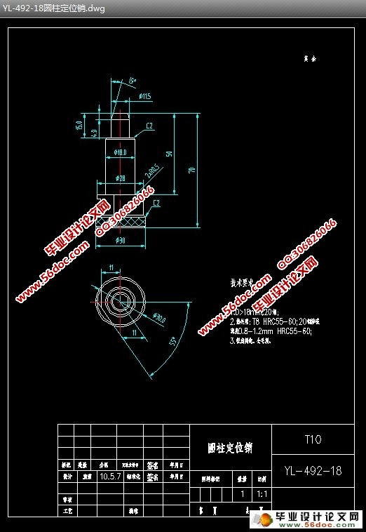
本设计是针对现实工厂中492发动机曲轴箱的加工过程中钻工艺孔(上下面共6孔)这道工序的夹具设计。根据492发动机曲轴箱的结构特点和生产中采用组合式钻床,该工件重达30Kg,夹具又采用钻套对刀,这时夹具如同一抽屉形式从侧面推进,在夹具主体上加一导轨支持装置和粗定位元件,以便快速准确定位。本夹具采用一面两孔定位原则即一个圆柱定位销、一个削边定位销和平面型支承板进行定位。
通过对各零件的误差和结构计算与分析。从总的看,本组合式钻床夹具能够满足生产要求,可以投入生产中应用,达到了设计的要求。
关键词:夹具设计;定位;夹紧
492 Engine Crankcase Relief Hole Drilling Fixture Design
Abstract: Machine tool fixture consists of positioned element, gripping holder, tool components, the specific part of the clip. Machine fixture design is aims at fixture parts.
The fixture design is for 492 engine crankcase hole drilling process (on the following 6 holes) in factory. According to the structural characteristics of the 492 engine crankcase, combined drilling and the workpiece weighs 30Kg, the fixture using drilling set on the knife, then the fixture as a drawer. So a coarse positioning devices and a rail support device are to be added on the fixture in order to quick and accurate positioning. The fixture uses one side and two bores principle that a cylindrical pin, a cutting edge and flat-type pin bearing plates to locate.
From the general, through the calculation and analysis of the errors and the structure, the combined drilling jig meets production requirements, the application can be put into production to achieve the design requirements.
Key words: Fixture design; Positioning; Clamp
目 录
摘要 1
关键词 1
1 绪论 2
1.1 机床夹具的背景及发展趋势 2
1.2 机床夹具的分类 3
1.3 钻床夹具的结构特点 5
1.4 课题的作用与意义 5
2 总体方案的研究 6
2.1 产品零件加工部位的技术要求 6
2.2 总体结构及工作原理 6
2.2.1 总体结构 6
2.2.2 工作原理 7
3 夹具的总体设计 8
3.1 定位装置 8
3.1.1 定位方案的研究与确定 8
3.1.2 定位元件的选择 9
3.2 对刀装置 14
3.2.1 夹具的对刀分析 15
3.2.2 对刀元件的设计 17
3.3 夹紧装置 18
3.3.1 工件达到正确夹紧的原则 19
3.3.2 夹紧机构的确定 20
3.3.3 夹紧力方向的确定 21
3.3.4 夹紧力作用点的确定 21
3.3.5 夹紧力大小的确定 21
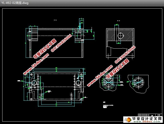
3.4 夹具体 22
3.4.1 夹具体的基本要求 22
3.4.2 夹具的定位 22
3.5 夹具总图上的尺寸、公差和技术要求 23
4 误差计算 23
4.1 定位误差的基本概念 23
4.2 定位误差的计算 24
5 结论 24
参考资料 26
致谢 27
|