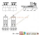
摘要:本组合机床是气缸盖半精镗、精镗组合机床,在完成 “三图一卡”的基础上,主要完成夹具设计。这个课题来源于江苏高精机电装备有限公司,是为了适合流水线生产,提高目前的生产效率、加工精度,从而降低加工成本而设计的。在设计过程中借鉴了国内外一些现有的组合机床设计资料,还参考了一些与本课题相关的文献资料。
设计的主要内容为组合机床的总体设计和夹具的设计。夹具的设计是本次设计中一个重要的部分。在夹具设计方面,首先,原有机床采用多工序加工,加工效率低,加工尺寸不容易保证,而且位置精度也不高。改进后,采用一次装夹,同时对进气和排气孔进行镗加工,提高了加工效率。其次,夹具采用一面两销定位,保证了导管孔及气门阀座孔对定位销孔的位置精度。夹紧方式采用液压夹紧,改变了原来的手动夹紧,提高了工作的效率。最后,对相应部分进行了计算、分析、校核。
本组合机床具有提高生产效率,满足工件的加工精度,减少了工人的劳动强度的优点,较好的实现了设计的要求。
关键词:组合机床;夹具;定位;夹紧
The modular machine tool design for half finished and finished boring of cylinder cap pipe hole (jig design)
Abstract: The modular machine-tool is defined as half finish and full finish boring machine with cylinder lids. In addition to the accomplishment of “Three drawings and one card”, the major task is to finish the design of jigs. The project originally from Jiangsu Gaojing Mechanical & Electrical Equipment CO.,LTD. Ltd aims to cater to the assembly line and improve effectiveness and processing precision so as to reduce the cost. During the process of design, I drew lessons from international and national data, and referenced some literature material related to the topic.
The designs cover the overall ones of the assembled machine and jigs. Firstly, as far as jig design, the main part of the designs, is concerned, the original machine tool has characteristic of multi working procedure machining, effectiveness, difficult machining size guarantee, and low location precision. After being improved, both the air inlet louver and outlet louver are bored by jigging just once, which not only improves effectiveness but also guarantees machining hole sizes. Next, in order to ensure the process precision and production efficiency of boring machine tool ,the jig uses ‘one surface-two sell’ .the way of Clamps is hydraulic pressure clamping, which replaced by Manual clamping. It can enhanced the work efficiency. At last, carry on the computation, the analysis, the examination to corresponding parts.
The advantages of this modular machine-tool are production efficiency, high precision of processing, reducing labor intensity of the workers.
Key words:modular machine-tool; jig; location; clamping
本设计的课题是气缸盖半精镗、精镗组合机床及夹具设计。这个课题来源于江苏高精机电装备有限公司,是针对该公司对气缸盖半精镗,精镗组合机床加工,其工作效率和精度不高而设计的。主要是为了适合流水线生产,提高目前的生产效率、加工精度,从而降低加工成本。
组合机床一般都由支承部件(床身、立柱、底座和中间底座)、动力部件(动力滑台和主轴头、动力头)、工件定位夹压和运送部件(夹具、回转工作台、移动工作台、鼓轮等)和控制部件(电气柜、液压站、操纵台等)组成。组合机床是根据工件加工的需要,以大量的通用部件为基础,配以少量的专用部件组成的一种高效的专用机床。组合机床一般采用多轴、多刀、多工序、多面或多工位同时加工的方法,生产效率比通用机床高几倍到几十倍。由于通用部件已经标准化和系列化,可根据需要灵活配置,能缩短设计和制造周期。因此,组合机床有低成本和高效率的优点,在大批、大量生产中得到广泛运用,并可用来组成自动生产线。多年来机械产品加工中广泛的采用万能机床,但是随着生产的发展,很多企业的产品的产量越来越大,精度越来越高,采用万能机床加工已经不能很好的满足要求。理所当然,生产着用机床可以提高生产效率和加工精度。在组合机床设计过程中,为了降低组合机床的制造成本,应尽可能的使用通用件和标准件。目前,我国设计制造的组合机床,其通用部件和标准件约占零件总数的70—80%,其它20—30%是专用零件。


目 录
1 前言……………………………………………………………………………1
2组合机床工艺方案的拟订………………………………………………………………3
2.1本机床加工零件的加工工序及加工精度……………………………………………3
2.2被加工零件特点…………………………………………………………………3
3组合机床的配置形式选择……………………………………………………4
4组合机床的总体设计……………………………………………………………………5
4.1被加工零件工序图……………………………………………………………5
4.2加工示意图………………………………………………………………6
4.2.1刀具的选择……………………………………………………………………7
4.2.2组合机床切削用量的选择………………………………………………………7
4.2.3计算切削力,切削扭矩及切削功率………………………………………………9
4.3机床联系尺寸图…………………………………………………………………11
4.3.1动力滑台的选择………………………………………………………………12
4.4机床生产率计算卡…………………………………………………………12
5 夹具的设计……………………………………………………………………16
5.1概述……………………………………………………………………………16
5.1.1机床夹具在机械加工中的作用………………………………………………16
(毕业设计)
5.1.2机床夹具的分类…………………………………………………………17
5.1.3机床夹具的组成………………………………………………………………17
5.1.4本次毕业设计的任务…………………………………………………………17
5.2夹具的设计步骤及内容…………………………………………………………17
5.2.1气缸盖镗孔工艺分析…………………………………………………………17
5.2.2夹紧方案的分析……………………………………………………………18
5.2.3夹紧力的确定与计算……………………………………………………………19
5.2.4夹紧液压缸的选择……………………………………………………………19
5.2.5定位元件的设计………………………………………………………………20
5.2.6定位误差的计算………………………………………………………………20
5.2.7导向装置的选择…………………………………………………………………21
5.2.8夹具体的设计……………………………………………………………………22
5.2.9其它元件的设计 …………………………………………………………………… 22
5.2.10夹具的精度设计……………………………………………………………………22
6 齿轮和轴的校核……………………………………………………………………… 25
6.1齿轮的校核……………………………………………………………………………25
6.2轴的校核………………………………………………………………………………27
7零部件的设计绘制 …………………………………………………………………… 32
7.1绘制加工零件工序图…………………………………………………………………32
7.2绘制加工示意图………………………………………………………………………32
7.3绘制夹具装配图及其零件图…………………………………………………………32
8 结论…………………………………………………………………………………… 33
参考文献………………………………………………………………………………… 34
致谢……………………………………………………………………………………… 35
附录……………………………………………………………………………………… 36 |


