升降器箱体机械加工的工艺规程编制及夹具设计(含CAD零件图夹具图)(论文说明书18000字,外文翻译,CAD图6张)
摘 要
机械加工工艺的学科是设计机械加工工艺的过程以及其加工当中所使用夹具的设计为主的一门学科,实践的性能也要求比较强,就要求在学习其过程的当中能够紧密的和生产实践相联系在一起,也拥有比较强的综合的性能,
此次所设计的升降器箱体零件的工艺以及专用夹具的编制的内容:
第一步,对升降器箱体零件来进行工艺的考虑,内容就是升降器箱体零件的功用的研究以及专用夹具的研究,经过对升降器箱体零件的研究能够知道全尺寸检查升降器箱体零件的最基本的情况,而工艺的研究能够了解升降器箱体工件的所要加工的表面以及机械加工的要求。按照升降器箱体零件图所给出的机械加工的要求,敲定升降器箱体零件的毛坯的加工形式以及确定毛胚的尺寸。
其次,选取加工基面,考虑好机械加工的过程当中的粗加工基准以及精加工的基准。按照确定好的设计基准,编制零件的加工工艺的方案,一般编制两种机械加工工艺的方案,经过2种加工工艺方案相比较以及研究,然后选取能够使加工工件的几何的形状与加工尺寸的精度以及形状精度等技术的要求能够得到满足所加工零件要求的一种合理的加工工序。
最终,按照最后确定的加工方案,计算每一个工步的切削加工用量以及加工基本的工时,并且选取的加工机床以及刀具要和零件相合适。对于粗加工,还要校核该机床的功率。然后把设计的过程整理为图纸。
通过以上的概述,整个设计基本完成。
关键词:机械;机械加工工艺;专用夹具设计
Procedure Regulation Compilation and Fixture Design for Mechanical Processing of Lifter Box
ABSTRACT
The subject is the process of machining process, machining process design and the design of the machining fixture used as a discipline, practice the performance requirements are relatively strong, requires to practice and production closely linked together in the learning process, also has the strong comprehensive performance,
The design of the hydraulic valve body parts of the process and the preparation of special fixture:
The first step, the hydraulic valve bracket parts to process considerations, the content is the study of the function of the hydraulic valve bracket parts and special fixture, the study of the hydraulic valve bracket parts to know Hydraulic valve parts of the basic situation, and the research process can understand the support to the processing of workpiece surface and machining requirements. According to the mechanical hydraulic valve bracket parts diagram given requirements, processing form finalized hydraulic valve bracket parts of the blank and blank size.
Secondly, considering the selection of machining surface, rough machining process of machining the benchmark and the benchmark finishing. According to the design basis to determine the good, process of preparation of parts of the program, the general preparation of two mechanical processing technology scheme, after 2 processing scheme comparison and research, and then select It is a reasonable working procedure to meet the requirements of the machining parts by taking the geometric shape of the workpiece and the precision of the machining dimension and the precision of the shape
Finally, according to the final processing scheme, calculated every steps of cutting dosage and processing the basic working hours, processing machine and tool and select appropriate parts and for rough machining, but also check the power machine. Then the design process for the drawings.
Through the above overview, the whole design is basically completed
Key words: machinery; machining process; special fixture design
2 分析升降器箱体的零件图
2.1 升降器箱体工艺性的分析
2.1.1 升降器箱体结构功用分析
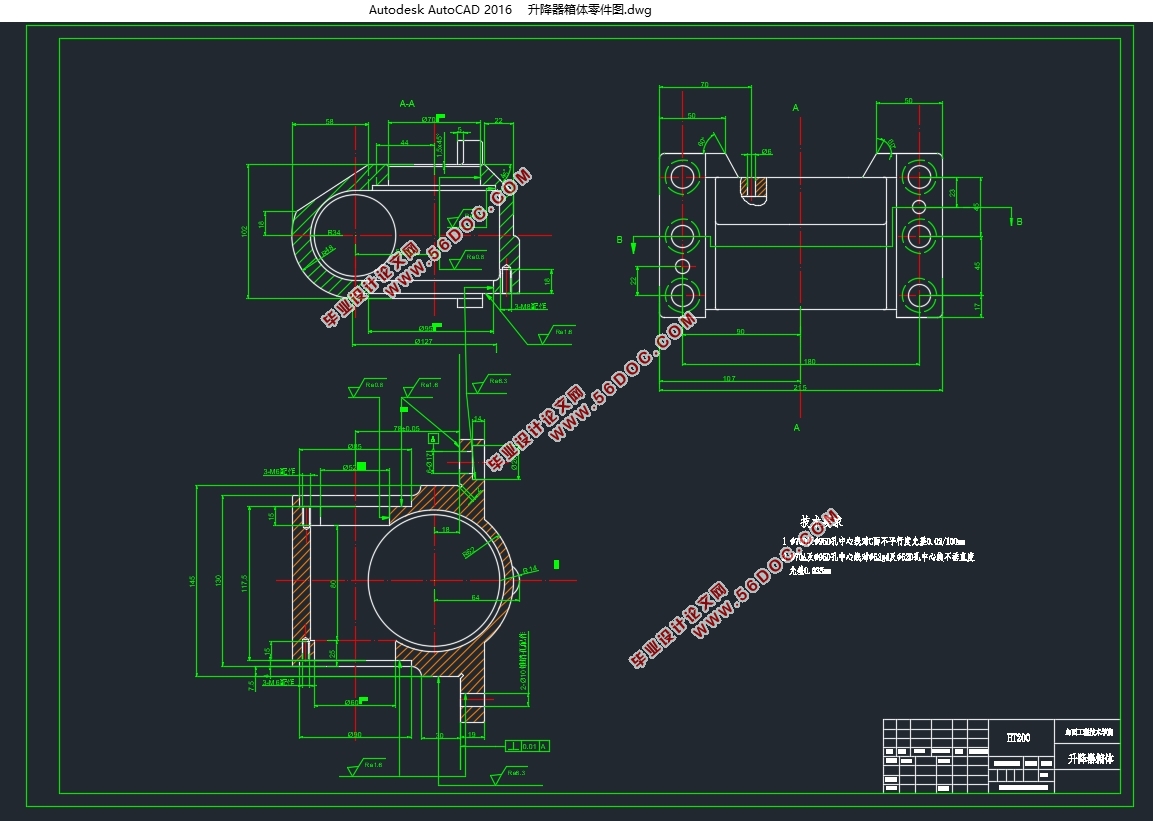
零件图是工程设计工人与机械加工工人之间语言对话的一种方法,因此它被叫做工程语言。根据所给的零件图,工人可以拟出相关的规程,来方便加工,该课题为升降器上的箱体零件的加工工艺及夹具设计,升降器箱体零件是起支撑固定,密封防尘的作用,而且承受非常大的力,也有着定位的作用,使各个零件之间能够持有合理的位置。所以,升降器箱体零件的加工的质量,直接就影响到机器的精度以及寿命。
2.1.2 零件结构工艺性分析:
零件的布局工艺性说的是满足正常使用的情况下,来想制造是不是可行,还有便是要尽量的省钱,还有他的生产效率的问题。零件结构工艺性分析可以联系下面这些方面:
1 有利于达到所需求的加工质量
(1)保证位置精度的可能性。
2 有利于减少不必要的加工面积
(1)尽可能减少不需要加工的面积;
(2)尽可能不去对内部表面加工。
3 有利于提高劳动生产率
(1)零件的有关尺寸应求一致,并能用标准刀具加工;
(2)减少零件的安装次数;
(3)零件的结构应便于加工;
(4)有利于许多工件同时加工。
我认为,升降器箱体的结构是属于中等复杂的那种。
(1)重要的面加工:
1)加工升降器箱体钻6-φ17mm孔以底平面及侧面为基准,保证180mm,45mm尺寸,位置度的误差达到0.03
2)镗φ52mm孔Φ60mm孔,以6-φ17mm孔,底平面为基准,保证工序尺寸及光洁度0.8要求。
3)铣19mm底平面, 定位的基准为背面与侧平面,保证工序尺寸19mm与光洁度为6.3
4)加工φ6mm的孔,以6-φ17mm孔,底平面为基准。
5)钻攻φ60孔端3-M8孔,以φ60孔,底平面为基准,,确保工序的尺寸与光洁度6.3
2.1.3 主要技术的条件:
①镗φ52mm孔Φ60mm孔的精度:φ52mm孔Φ60mm孔的尺寸与形状的误差,能够影响到升降器箱体工作的状态,因此对φ52mm孔Φ60mm孔的要求高,φ52mm孔Φ60mm孔的尺寸公差为
②铣19mm底平面的精度:因为铣19mm底平面对升降器箱体联接时的密封性能有影响,而且作为定位的加工基面,要不就可能对孔的加工的精度,具有非常大的影响,所以就要规定它加工的要求。

目 录
摘 要 i
ABSTRACT ii
1 绪论 1
2 分析升降器箱体的零件图 5
2.1 升降器箱体工艺性的分析 5
2.1.1 升降器箱体结构功用分析 5
2.1.2 零件结构工艺性分析: 5
2.1.3 主要技术的条件: 6
2.2 确定毛坯的结构 7
3 升降器箱体的加工工艺设计 8
3.1 选取加工基面 8
3.1.1 粗基准的选择 8
3.1.2 精基准选择的原则 9
3.2 零件各加工部位加工方法的选择 9
3.3 加工顺序的安排 10
3.4 制定工艺路线 12
3.5 机械加工余量、工序尺寸及公差的确定 14
3.5.1 毛坯的种类分析 14
3.5.2 毛坯的加工余量 14
3.6 设备及其工艺装备确定 15
3.7 确定切削用量及基本工时 16
4 夹具设计 29
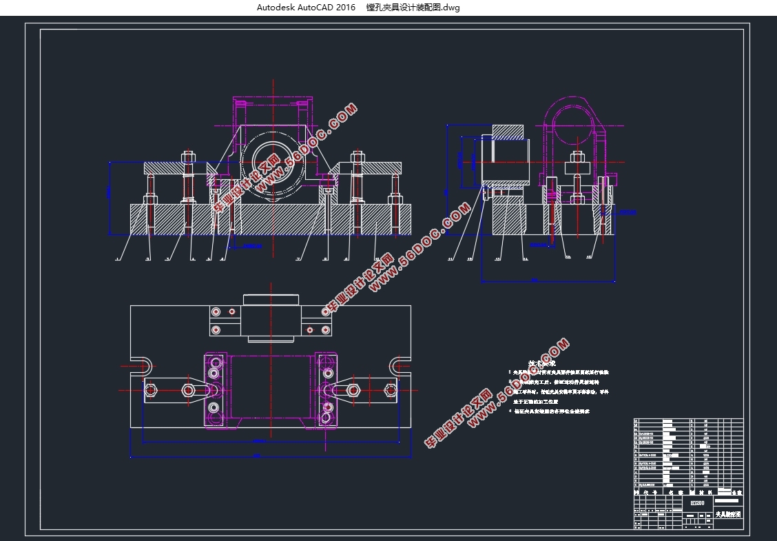
4.1 夹具设计要求 29
4.1 .1 设计夹具的基本要求 29
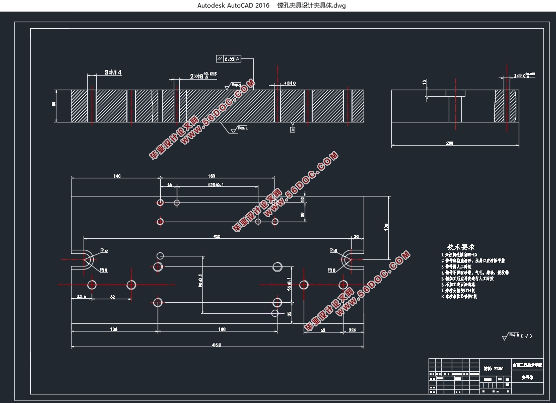
4.1.2 对夹具体的要求 29
4.3 铣升降器箱体底平面夹具设计 30
4.2.1 引出问题 30
4.2.2 原始质料的研究 30
4.2.3 选择使用定位的基准 30
4.2.4 研究计算切削力与夹紧力 31
4.2.5 研究误差和计算 32
4.2.6 夹具设计及操作的使用要说明 33
4.3 镗φ70孔φ95夹具 34
4.3.1 研究原始质料 34
4.3.2 定位基准的选择 34
4.3.3 切削力及夹紧分析计算 34
4.3.4 误差分析与计算 36
4.3.5 夹具设计及操作的简要说明 37
5 总结 39
参考文献 41
外文文献 43
中文翻译 48
致 谢 52
|