发动机连杆加工工艺和夹具设计(含CAD零件图装配图,工序卡,工艺卡)(论文说明书16000字,CAD图7张,工序卡,工艺卡)
摘 要
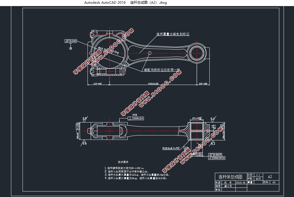
柴油发动机工作时,压缩冲程把燃油和空气的混合物压缩,使温度升高达到其燃点从而点火燃烧在气缸中产生热能,使活塞顶面产生膨胀的压力,此压力由连杆传递给曲轴,而连杆本身又受曲轴的来回推动带动活塞压缩气缸中的气体。在工作中连杆承受着剧烈变化的动载荷。由于连杆在设计过程中要求的尺寸精度、形状精度和位置精度很高,而且连杆的刚性不是很好,很容易发生工件的变形,所以很难达到零件的技术要求。
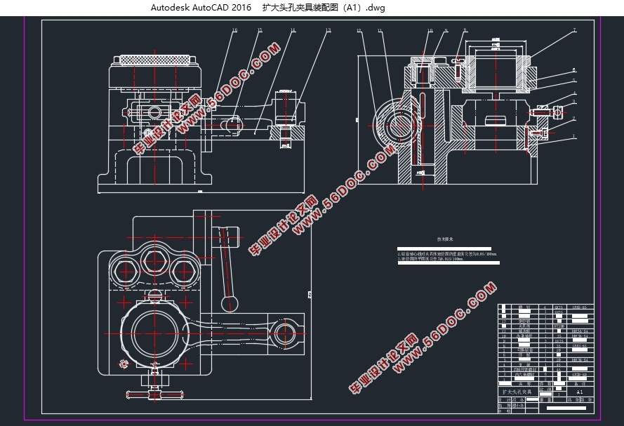
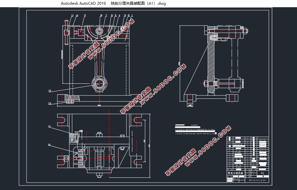
本论文进行了连杆工艺及其专用夹具的设计工作,具体如下,在设计过程中,以路虎神行者2TD4柴油机为例进行连杆的设计,首先对连杆的结构特点进行分析,来确定连杆的材料和毛坯、以及所需的技术条件,从而确定连杆最佳的设计流程和加工工艺,并分别对连杆的各个端面及大小头孔进行了工序设计,其次是对连杆主要的专用夹具进行设计,根据连杆的加工条件和技术要求,对连杆的铣剖分面夹具和扩大头孔夹具进行了详细的设计,并分别从工件定位及夹紧方案的选择、切削力和夹紧力的计算、工件和夹具之间的定位误差的确定等方面进行了全面设计。
通过对连杆的机械加工工艺和夹具的三维模型设计,使其在生产过程中用料更加节约,装夹更加便捷,对实际的生产过程具有重要的意义。
关键词:连杆 变形 加工工艺 夹具设计
Abstract
When the diesel engine works,the compression stroke takes a mixture of fuel and air compression.It makes the temperature higher,and reaches its flash point,and burns in the cylinder to produce heat.The top surface of piston brings the expansion of the pressure which is passed to the crankshaft by the connecting rod.At the same time,the connecting rod itself drives the piston to cut down the gas in cylinder. Since the dimensional accuracy required for the link in the design process, the shape and positional accuracy is very high, and the rigidity of the link is not very good, it is prone to deformation of the workpiece, it is difficult to meet the technical requirements of the part.
In this paper, the design of the connecting rod technology and the special fixture is designed,we take the land rover free lander 2TD4 diesel engine as an example, First analyzed the structure characteristics of the connecting rod, to determine the connecting rod materials and blank, as well as the necessary technical conditions, to determine the best design process and processing technology of the connecting rod, and on every end of the connecting rod and the size of the head hole for the process design, the second is to link the main special fixture design, according to the processing conditions and technical requirements of connecting rod, profile control of connecting rod milling faceted clamp and expanding hole in detail design, respectively from the workpiece positioning and clamping scheme selection, cutting force and the calculation of clamping force, between the workpiece and fixture of the aspects of the position error of the overall design.
Through the connecting rod of three-dimensional model of process optimization and fixture design, make its more savings in the process of production materials, the clamping more convenient, has the vital significance to the actual production process.
Key words:Connecting rod;deformation;processing technology;fixture design
目 录
摘 要 I
Abstract II
第一章 绪论 1
1.1研究背景和意义 1
1.1.1研究背景 1
1.1.2研究意义 1
1.2国内外研究现状及发展 1
1.2.1国内外发展现状 1
1.2.2国内外发展趋势 2
第二章 连杆零件分析 3
2.1连杆零件的结构特点及其材料 3
2.1.1柴油机连杆的工作条件 3
2.1.2连杆的材料 3
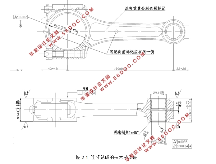
2.1.3连杆的主要技术要求 3
2.2连杆零件的工艺分析 4
2.2.1工艺过程安排 4
2.2.2连杆的加工精度 4
2.2.3定位基准的选择 5
2.3连杆裂纹主要原因剖析 6
2.3.1技术要求 6
2.3.2原材料的影响 6
2.3.3化学成份的影响 6
2.4本章小结 7
第三章 连杆工艺规程设计 8
3.1连杆材料和毛坯的选择 8
3.2基面的选择 8
3.2.1粗基准的选择 9
3.2.2精基准的选择 10
3.3工艺路线制定 10
3.3.1工艺特点分析 10
3.3.2工艺方案确定 10
3.4确定机械加工余量 12
3.5确定工序尺寸及其公差 13
3.6计算工艺尺寸链 14
3.7确定切削用量及基本工时 15
3.7.1切削用量的确定 15
3.7.2工时定额的计算 16
3.8本章小结 33
第四章 连杆夹具设计 34
4.1夹具的基本概述 34
4.1.1机床夹具的定义和组成 34
4.1.2机床夹具的功能 34
4.2铣剖分面夹具设计 34
4.2.1工件的定位及夹紧 35
4.2.2切削力及夹紧力的计算 36
4.2.3定位误差分析 36
4.3扩大头孔夹具设计 37
4.3.1工件的定位及夹紧 37
4.3.2切削力及夹紧力的计算 38
4.3.3定位误差分析 39
4.3.4三维装配图Pro/E建模 40
4.4本章小结 41
第五章 总结与展望 42
5.1总结 42
5.2展望 42
参考文献 43
致谢 45
|