4125型四缸柴油发动机缸体定位孔钻铰加工及工艺装备设计(含CAD零件图夹具图)(任务书,开题报告,外文翻译,论文说明书11000字,CAD图4张)
摘 要
本课题是对4125型柴油机缸体的定位孔进行钻铰加工及工艺装备设计。
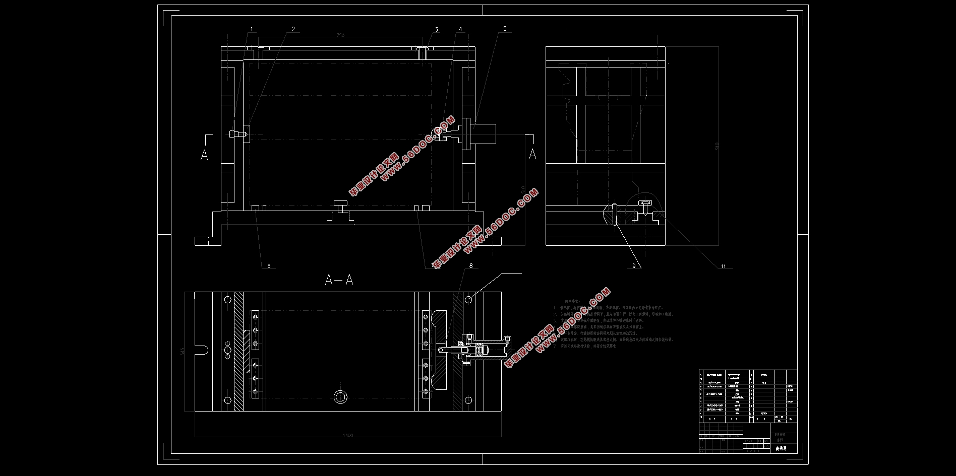
论文主要是钻铰缸体定位孔组合钻床的设计和钻铰缸体定位孔组合钻床专用夹具的设计,通过对零件的结构分析和工艺分析,确定了钻床的基本配置型式和切削用量。并且完成组合机床的总体设计即三图一卡的设计,其中三图一卡中的三图指的是加工零件的工序图,加工零件示意图和机床的联系尺寸图,一卡即年生产量卡。完成之后,联系所学的夹具设计知识,并设计组合机床的专用夹具,根据缸体加工精度的要求,来设计组合机床专用夹具的定位装置,夹紧装置,对刀和引导装置,并进一步考虑夹具体的设计,通过材料的选择及加工要求完成总体的计算后,用AutoCAD草绘出三图和夹具体的总体装配图。
通过钻铰缸体定位孔组合机床和钻铰缸体定位孔组合机床专用夹具的设计,提高了零件的加工精度,并提高了生产率,保证了生产安全,减轻了工人的劳动强度。
关键词:气缸体,零件分析,组合机床,三图一卡,AutoCAD,组合机床专用夹具。
Abstract
This project is to drill and ream the locating hole of 4125 diesel engine block and design the process equipment.
This paper is mainly about the design of the combined drilling machine for locating hole of the drilling cylinder body and the design of the special fixture of the combined drilling machine for locating hole of the drilling cylinder body.And complete the overall design of the combined machine tool, namely the design of three-picture and one-card, among which the three-picture of the three-picture card refers to the process diagram of machining parts, the schematic diagram of machining parts and the size diagram of the machine tool, and the one-card is the annual output card.Completed, contact of fixture design knowledge, and special fixture design of modular machine tool, according to the requirements of machining precision and to design special fixture combination machine tool positioning device, clamping device, the knife and guiding device, and further to consider carefully the specific design, through the choice of materials and processing requirements after completion of the overall calculation using AutoCAD draw three grass diagram and the specific general assembly drawing.
Through the design of the combination machine for drilling the hinged cylinder block positioning hole and the special fixture for the combination machine for drilling the hinged cylinder block positioning hole, the machining accuracy of the parts is improved, the productivity is increased, the production safety is guaranteed, and the labor intensity of the workers is reduced.
Key Words:Cylinder block, parts analysis, modular machine tool, three picture one card, AutoCAD, modular machine tool special fixture.
零件的结构和工艺分析
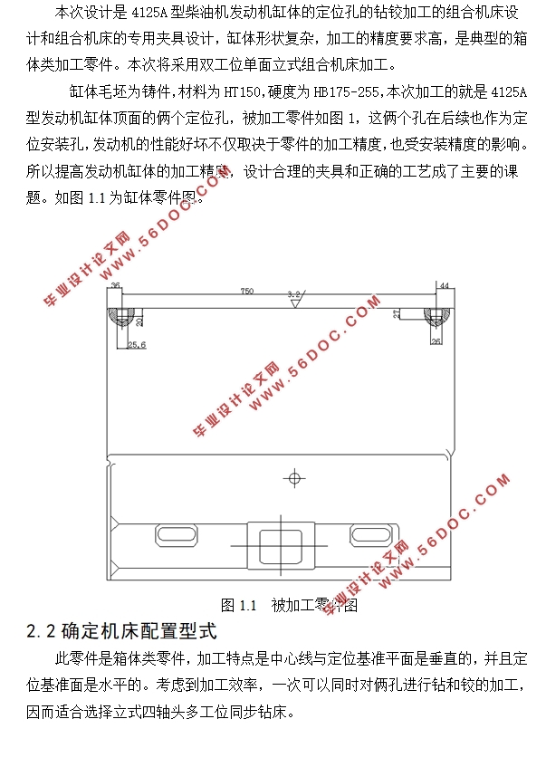
本次设计是4125A型柴油机发动机缸体的定位孔的钻铰加工的组合机床设计和组合机床的专用夹具设计,缸体形状复杂,加工的精度要求高,是典型的箱体类加工零件。本次将采用双工位单面立式组合机床加工。
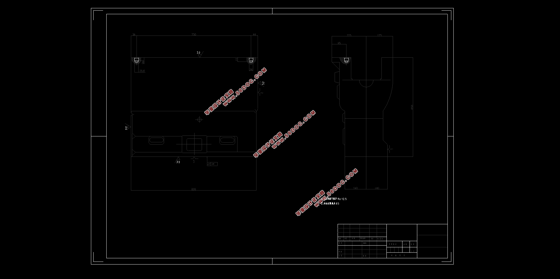
缸体毛坯为铸件,材料为HT150,硬度为HB175-255,本次加工的就是4125A型发动机缸体顶面的俩个定位孔,被加工零件如图1,这俩个孔在后续也作为定位安装孔,发动机的性能好坏不仅取决于零件的加工精度,也受安装精度的影响。所以提高发动机缸体的加工精度,设计合理的夹具和正确的工艺成了主要的课题。
零件的加工技术要求
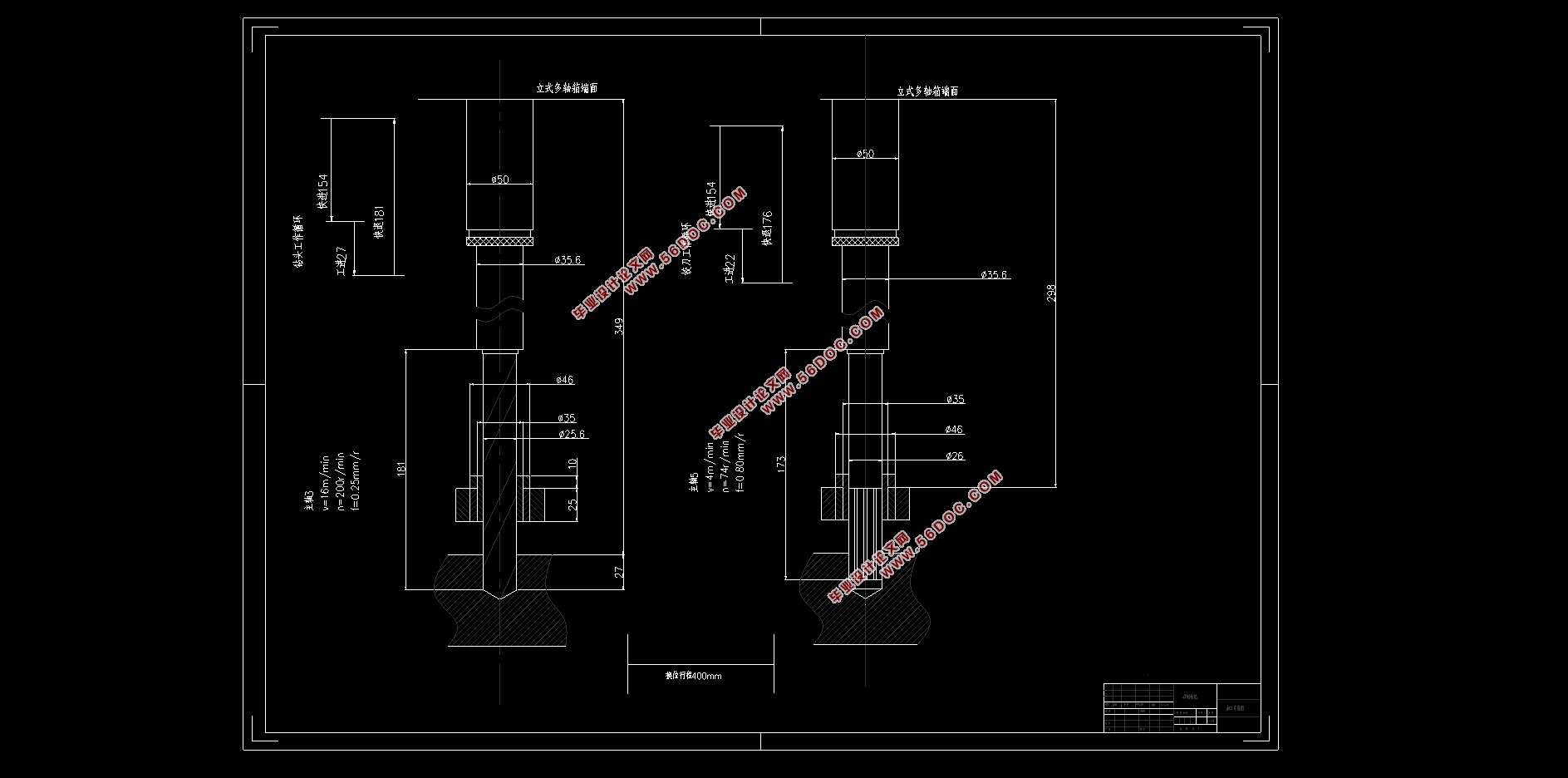
本次加工是对汽缸体的俩定位孔进行先钻后铰加工,这个孔后续也作为定位安装孔,钻孔孔径为25.6mm,孔深为27mm,铰孔孔径为26mm,孔深为22mm。表面粗糙度Ra=3.2um。

目录
摘要............................................................1
关键词..........................................................1
第1章 绪论.....................................................4
第2章 被加工零件的分析.........................................5
2.1 被加工零件结构和工艺分析................................5
2.2确定机床的配置型式.......................................5
2.3 零件加工技术要求........................................6
2.4 零件生产纲领和类型......................................6
第3章 钻铰缸体定位孔组合机床的设计.............................6
3.1影响组合机床制定的因素..................................6
3.2确定切削用量及选择道具..................................7
3.3三图一卡的制定..........................................8
3.3.1被加工零件工序图的内容和作用.......................8
3.3.2绘制被加工零件加工示意图注意事项...................8
3.3.3加工零件示意图.....................................9
3.3.4机床联系尺寸图.....................................11
3.3.5生产效率卡.........................................13
第4章 钻铰缸体定位孔专用夹具的设计.............................15
4.1专用夹具总体............................................15
4.1.1夹具基本组成.......................................15
4.1.2夹具设计要点.......................................15
4.2钻铰缸体定位孔的夹具设计................................16
4.2.1 零件本工序的加工要求分析
4.2.2 夹具整体类型的确定
4.2.3拟定定位方案和定位原件.............................17
4.2.4确定夹紧方案.......................................18
4.2.5 拟定夹紧原件和夹紧机构.............................18
4.2.6夹紧力的分析和计算.................................19
4.2.7夹紧油缸的选用.....................................20
4.2.8对刀装置的设计.....................................20
4.2.9引导装置的设计.....................................21
4.2.10夹具体外形结构尺寸的设计..........................21
5总结..........................................................22
参考文献........................................................22
致谢............................................................23
|