汽车后桥减速器壳夹具设计(含CAD零件图装配图,SolidWorks三维图)(任务书,开题报告,文献摘要,外文翻译,论文说明书16000字,CAD图8张,SolidWorks三维图)
摘 要
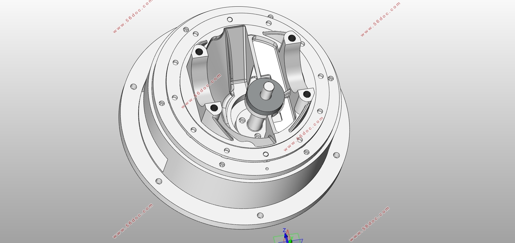
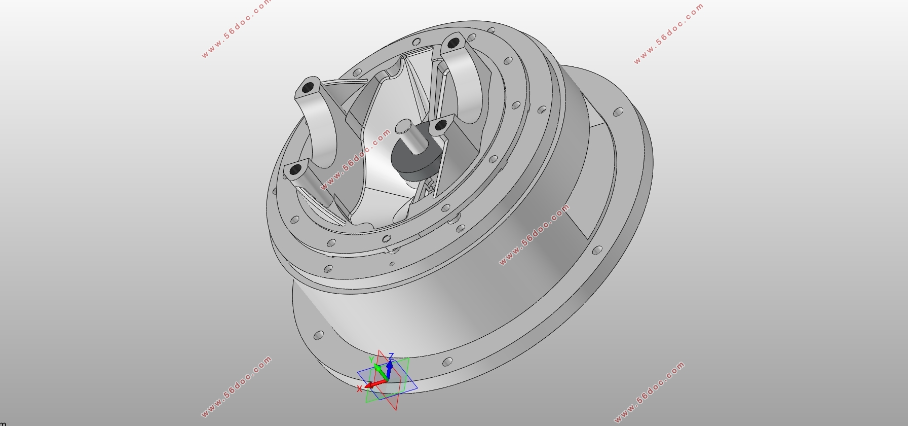
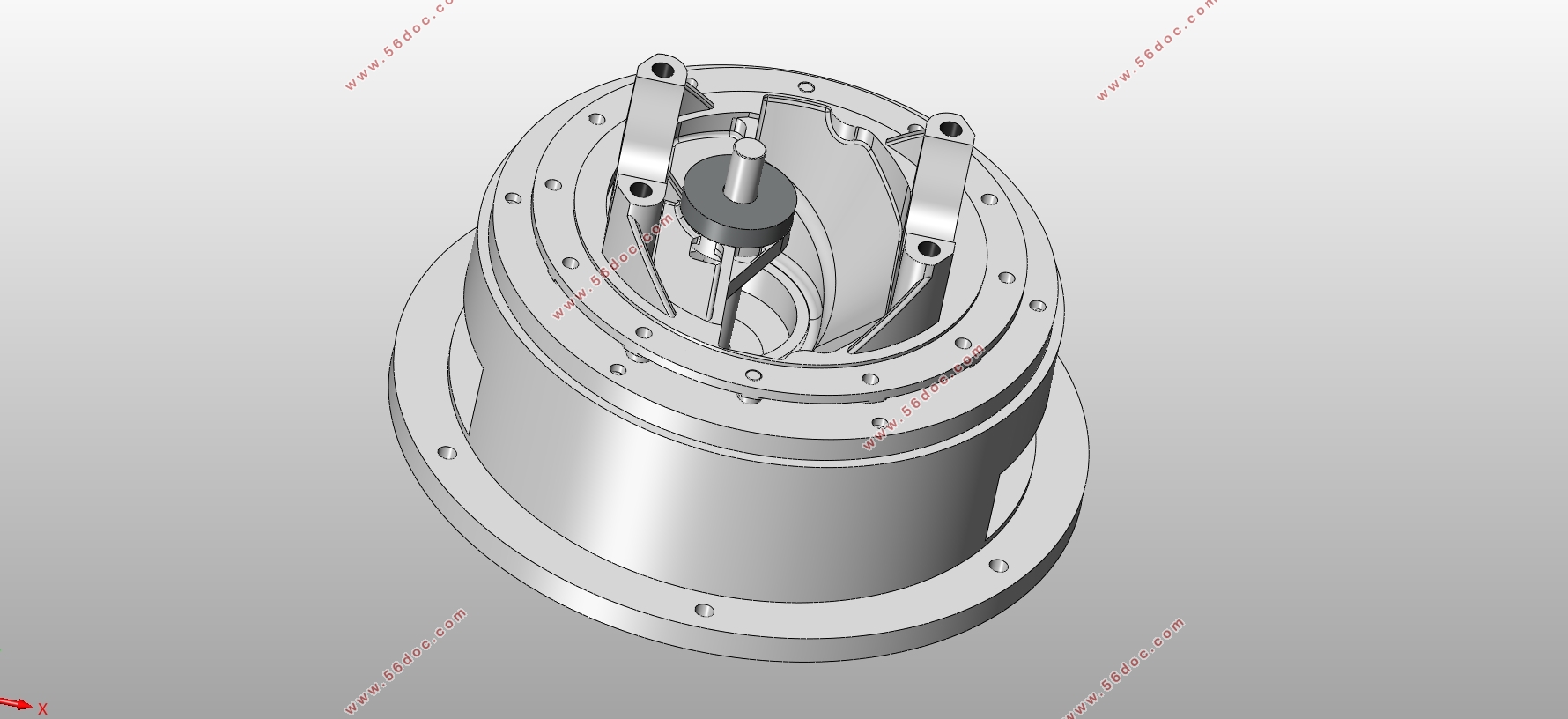
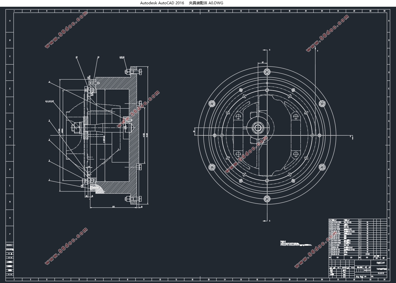
本次毕业设计是完成TF4-2303050汽车后桥减速器壳总成生产线工序一,即粗车减速器壳法兰面及止口和盖体结合面所需的手动夹具的设计。在设计之前通过查阅相关书籍、网上收集资料等方式充分了解了夹具领域现状及未来发展趋势,了解并认识到机床专用夹具具有提高产品的生产率及降低其生产成本、保证机床的加工精度、扩大机床的工艺范围,同时能减轻工人劳动强度等诸多优点。尤其是对于外形结构不规则的零件而言,机床专用夹具不可或缺。然后通过设计任务及原始资料分析零件结构及尺寸精度,根据工序要求,确定几种可行的夹具定位方案,比较各种方案定位误差然后从中确定最优方案,最终确定以减速器壳法兰面部分下端面及该部分两孔作为定位的定位方案。之后围绕夹紧方案、工艺规程制定进行详细论述,讲述定位误差计算、夹紧方案设计等。并同时完成切削力、夹紧力的计算以验证方案。此外,还完成了零件及夹具部件模型创建以及相关动画(爆炸动画和加工模拟动画等)。
关键词:汽车后桥减速器壳总成;手动夹具;专用夹具;定位误差;夹紧
Abstract
This graduation design is to complete the design of the needed manual fixture of the process line 1 of TF4-2303050 car rear axle reducer shell assembly, that is, rough cutting reducer shell flange and the seam allowance and the cover joint surface. Before the design, I fully understand the status of fixture and the future development trends through access to relevant books, online collection of information, etc. And I understand and realize that the machine tool fixture has the advantages of improving the product productivity and reducing its production cost, ensuring the machining precision of the machine tool, enlarging the process Range of the machine tool and reducing the labor intensity of the workers. Especially for the irregular shape of the parts, the machine-specific fixture is indispensable. Then, through the task of this design and the original data analysis of the structure and dimensional accuracy of the parts, according to the requirementsof the process, I determine several feasible fixture positioning programs. By comparing the various program positioning error and then I determine the optimal program, and ultimately choose the positioning program, which use the lower end face of reducer shell flange part and the two holes as the positioning. Finally, I process planning around the clamping program to elaborate on the positioning error analysis, clamping design and so on. And in this process,I complete the cutting force, clamping force calculation to verify the program.In addition, parts and fixture parts model creation and related animation (exploding animation and machining simulation animation) have been completed.
Key Words: Automotive rear axle reducer shell assembly; Manual fixture;Special fixture;Positioning error;Clamping force
加工零件的所有加工工序
我设计的夹具是加工TF4-2303050减速器壳总成(含TF4-2303052减速器壳盖的加工及减速器壳组装后的加工)生产线工序一所需的夹具。加工TF4-2303050减速器壳总成的工序共7个,工序如下:
工序一:粗车减速器壳发兰面及止口和盖体结合面
工序二:钻、铰减速器壳法兰面孔,钻攻轴盖结合孔
工序三:粗精铣减速器轴盖底面、上面及钻扩2-φ22H6mm孔倒角
工序四:组装
工序五:精车减速器壳总成发兰面、止口和20°倒角面
工序六:粗镗减速器壳总成主动轴孔和从动轴孔
工序七:精镗减速器壳总成主动轴孔和从动轴孔
此处只对我设计的工序一进行详述(如下),其余各工序加工设备、夹具、检具见附件A机械加工工艺过程卡。
工序一:粗车减速器壳发兰面及止口和盖体结合面
加工设备名称:数控立车,数量一台。
加工设备型号:CK516。
加工部位:发兰面(留余量0.8)及止口(留余量1)和盖体结合面(到位)。
夹具:手动夹具,数量一套。
检具:通用检具。
目录
第1章绪论 1
第2章设计任务和原始资料 3
2.1 待加工零件的所有加工工序 3
2.2 生产纲领 3
2.3 零件 4
第3章零件的工艺分析及定位方案的确定 5
3.1 零件的工艺分析 5
3.2 定位方案的确定 5
3.3 定位误差分析 8
第4章零件夹紧方案的确定 12
4.1 切削力的计算 12
4.2 夹紧方案的确定 14
4.3 夹紧力的计算 16
5 零件工艺规程的制定 19
5.1 加工余量和工序尺寸的确定 19
5.1.1 查表确定加工余量 19
5.1.2 计算各工序尺寸的基本尺寸 19
5.1.3 确定各工序尺寸的公差及偏差 19
5.2金属切削刀具和量具的确定 20
5.2.1刀具材料的选定 20
5.2.2 量具的确定 20
5.3 机床的选用 21
5.4切削用量的选择 22
总结 23
参考文献 24
附件A 机械加工工艺卡片 25
致谢 26
|