簧片落料弯曲级进模设计
来源:56doc.com 资料编号:5D10892 资料等级:★★★★★ %E8%B5%84%E6%96%99%E7%BC%96%E5%8F%B7%EF%BC%9A5D10892
资料介绍
簧片落料弯曲级进模设计(论文说明书23000字,外文翻译,cad图纸7张) 摘要
冲压是利用安装在冲压设备(主要是压力机)上的模具对材料施加压力,使其产生分离或塑性变形,从而获得所需零件的一种压力加工方法。弯曲是将板料、棒料、管材和型材弯曲成一定角度和形状的冲压成形工序。
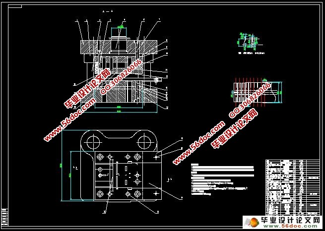
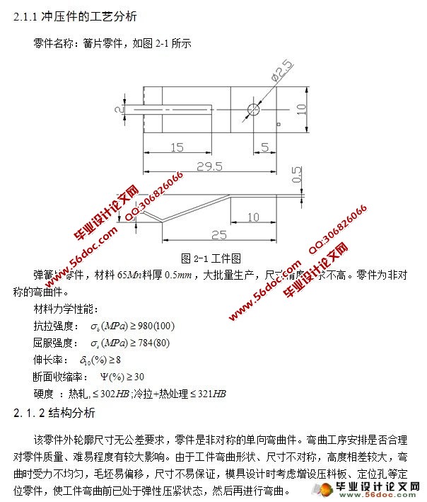
本文研究的是簧片落料弯曲级进模设计。首先进行工艺性分析,确定最佳加工工艺,并对进行工艺计算,根据工件的尺寸及结构关系进行模具设计,比如在弯曲过程中对于回弹值的确定等。对主要结构零件进行了设计计算和强度校核;最后又确定了落料、弯曲级进模的结构型式,对零件进行了设计和校核,并合理的选择了压力机。
关键词 簧片;级进模;冲压工艺;模具设计
Abstract
Stamping is installed in the use of stamping equipment (mainly press) on the mold to exert pressure on the materials to produce plastic deformation or separation, to obtain the necessary components of a pressure processing methods. Sheet metal bending is, bar, pipe-bending and profiles some perspective and shape of the stamping process.
This study is the reeds blanking bending of progressive die design. First analysis, determined the best technology processing technology, and for process calculation, according to the size of workpiece and structural relationship, for instance in bending tooling design process of the determination of for rebound value. Major structural parts of the design calculation and strength check; Finally and determine the blanking, bending the structural type of progressive die for parts, the design and check, and reasonable chose press.
Keywords spring piece Rebound value Stamping process Mold design
     目 录
摘要 I
Abstract II
1 绪论 1
1.1 课题研究的背景 1
1.2 冲压模具行业发展现状及趋势 1
1.3级进模的特点 4
1.5课题研究的主要内容 4
2.冲压工艺分析 5
2.1冲压工艺分析 5
2.1.1冲压件的工艺分析 5
2.1.2结构分析 5
2.1.3 加工顺序决定的的毛坯原则 5
2.1.4 冲压方案设计 6
2.2 确定排样图 7
2.2.1 排样图的设计与计算 7
2.2.2 排样图设计原则 7
2.2.3 排样图 7
3 计算各工序冲压力和选择冲压设备 9
3.1 落料、冲压级进模的冲压力计算和设备选择 9
3.1.1冲压力的计算 9
3.1.2选用冲压设备 10
3.1.3冲模压力中心的确定 10
3.1.4模具闭合高度的确定 10
3.2凸、凹模设计 11
3.2.1冲裁凸凹模的设计原则 11
3.2.2确定凸、凹模间隙 12
3.2.3凸、凹模刃口尺寸确定 13
3.3 冲裁模具的设计和设备的选择 14
3.3.1 冲裁模的分类 14
3.3.2 凸模、凹模的结构设计 15
3.3.3弯曲变形过程 16
3.3.4弯曲质量分析 16
3.4弯曲工艺计算 20
4 模具的设计与装配 24
4.1 定位零件的设计 24
4.2卸料及压料零件设计与标准 24
4.3卸料螺钉及其它零件的的选择 25
4.4 模架及导套、导柱选择 26
4.5 模具设计 26
4.5.1 侧刃凸模 26
4.6选择冲压设备 28
4.6.1 冲压设备的选用原则: 28
4.6.2 压力机吨位和型号的选择 28
4.6.3 压力机的可用性分析 29
4.7模具总装图的绘制 29
4.8模具的装配 30
结论 34
致谢 35
参考文献 36
|