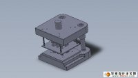
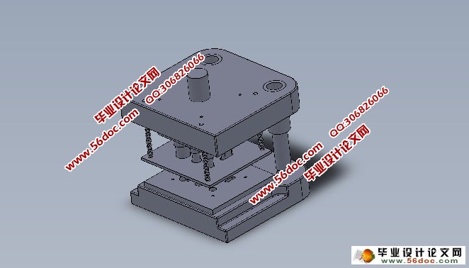
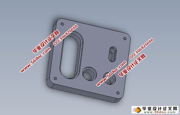
连接片冲孔、翻边、落料连续式复合模设计(CAD,SolidWorks三维)(选题审批表,任务书,开题报告,中期检查表,论文说明书10000字,CAD图纸12张,SolidWorks三维)
摘要:本文进行了连片冲孔、翻边、落料连续复合模设计,根据要求完成相应的任务。
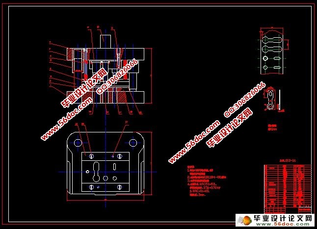
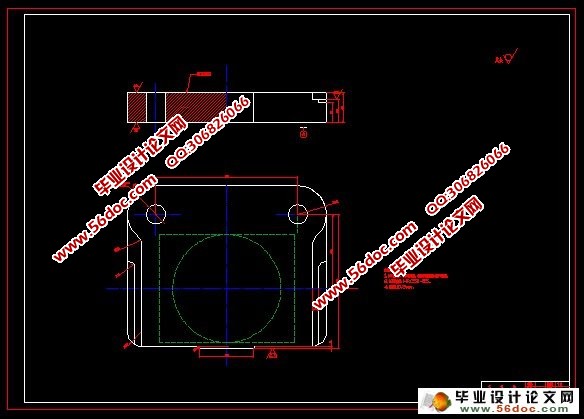
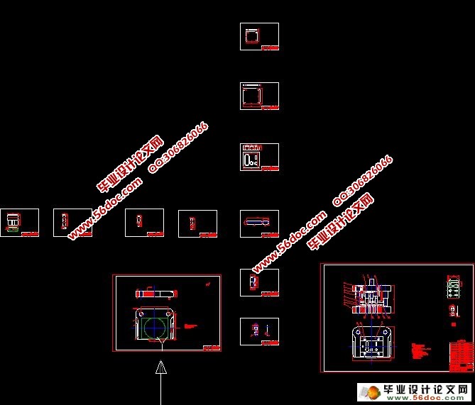
本文的主要内容有:取得必要的材料,并分析零件的冲压工艺性;确定模具的结构形式;进行必要的工艺计算;模具的总体设计;模具的主要零部件的结构设计;绘制模具总图;利用SolidWorks软件建立了连接片冲孔、翻边、落料连续式复合膜具全部零件的三维实体模型,并对其进行了虚拟装配。通过对它的虚拟样机设计,可以更好的了解它的结构和主要零部件。同时也可以将验证结构设计的正确性和合理性,为制作物理样机节省成本。
关键词:冲裁模具;计算;三维实体模型
Design of Connecting Piece Punching Flanging Blanking Successive Composite Membrane
Abstract: This article has conducted the sectors-connecting punching, flanging, blanking continuous compound mould design, according to the task of complete the required corresponding.The main content of this article: obtain necessary material, and analysis the stamping technology parts; sure die structure form; necessary process calculation; the overall design, mould the main parts of the mould structure design; drawing mould assembly drawing;SolidWorks software is built by connecting piece punching, flanging, blanking successive composite membrane with all components of the three-dimensional entity model, and analyses the virtual assembly. Through to its virtual prototype design, can better understand its structure and main components. Also can be used to verify the correctness and rationality of the design structure, for making physical prototype cost saving.
Key words:Punching mould; calculation; Three-dimensional entity model
目 录
摘要 1
关键词 1
1 前言 2
2 冲压工艺过程制定 3
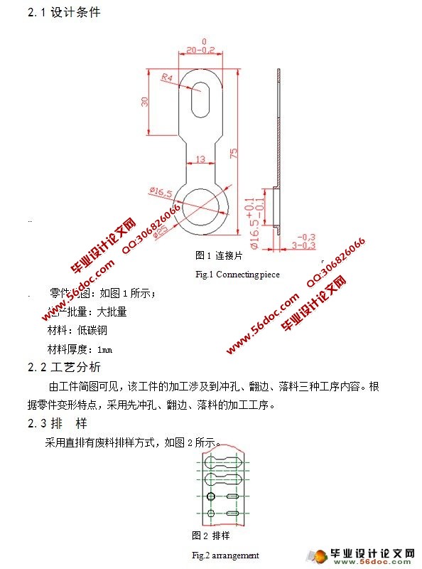
2.1 设计条件 3
2.2 工艺分析 3
2.3 排 样 4
2.4 计算翻边力 4
2.4.1 工艺分析 5
2.4.2 工艺计算 5
2.4.3翻边凸凹模径向尺寸的计算 5
2.5 计算冲裁力 6
2.5.1 冲裁力 6
2.5.2 卸料力 6
2.5.3 顶出力 6
2.5.4 总冲压力 6
2.5.5 计算凸凹模的刃口尺寸 7
2.6 计算冲压力 8
2.6.1冲裁力 8
2.6.2 卸料力 8
2.6.3 顶料力 8
2.6.4 总冲压力为 8
.2.6.5 计算凸凹模的刃口尺寸 8
2.7确定模具的压力中心 9
2.8 选择冲压设备 10
3 模具总体设计及主要零件设计 10
.3.1 固定零件 11
3.1.1 上、下模座 11
3.1.2 模柄 11
3.1.3 凸模固定板 11
3.1.4 垫板 12
3.1.5紧固及其他零件 12
3.2 导向零件 13
3.2.1导柱与导套 13
3.2.2导料板 13
3.2.4卸料板 13
3.2.5 弹簧 14
4 模具装配的工艺过程 14
4.1装配的技术要求 14
4.2模具的装配工艺过程 15
5 模具中的主要零部件的组装方法 15
5.1模柄的装配 15
5.2 导柱、导套的装配 15
6 冲裁模的调试 16
6.1 送料不通畅或被卡死 16
6.2 卸料不正常,退不下料 16
6.3凸、凹模的刃口相碰 16
6.5凹模被胀裂 17
6.6冲件的形状尺寸不正确 17
6.7落料外行和冲孔位置不正,出现偏移现象 17
6.8 冲件不平整 17
6.9 冲件毛刺较大 17
7 总结 17
参考文献 19
致 谢 20
|