侧弯支架多工位级进模设计(含CAD零件图和装配图)(精品)☆(选题审批表,任务书,开题报告,中期检查表,论文说明书14800字,CAD图34张)
摘 要:通过查找相关资料,利用相关电脑绘图软件进行设计。此模具能够实现切边、冲孔、弯曲、切舌等工序。并对此模具的结构、尺寸和形状、工作原理和受力情况进行设计研究。分析了侧弯支架零件的工艺性,介绍了侧弯支架多工位级进模的总体结构、主要零部件和排样方案。级进模具有结构紧凑、操作简单、生产效率高的特点,生产的零件符合要求。通过UG建模,修正设计的有关结构,有限元分析诠释了模具工作的可靠性。
关键词:弯支架;级进模;排样方案;模具设计
The Design Of Side Bend Bracket Multi-Position Progressive Die
Abstract:In order to design the subject, we search for relevant information and use the related to computer graphics design software. This mold can achieve trimming, punching, bending, cutting the tongue and other processes. And we also have done the design research of the mold structure, size and shape, the working principle and the stress situation. We have analyzed the side bend bracket parts of the process and introduced the side bend bracket of multi-position progressive die for the overall structure, main parts and the layout scheme. Progressive die has the advantages of compact structure, simple operation, and high production efficiency characteristics, to meet the requirements of production parts. Through the UG modeling, modification design on the structure, finite element analysis and interpretation of the die working reliability.
Key words:side bend bracket; progressive die; layout scheme; die design
设计的目的与要求
“侧弯支架多工位级进模设计”选题来源于生产实际现场。具有较强的实际应用价值。该课题能较好的让学生综合运用大学所学课程加以解决。通过该课题设计,可以达到培养学生正确的设计思想与设计方法,敢于创造革新;培养学生综合、灵活应用所学知识去分析研究和解决工程设计中遇到的一些工程技术问题;进一步提高学生调查研究、设计计算、理论分析、查阅资料及绘制图样等各方面的基本技能
目 录
摘要 …………………………………………………………………………………………1
关键词 ………………………………………………………………………………………1
1 前言………………………………………………………………………………………1
1.1 模具工业的概括 ………………………………………………………………2
1.2 设计的目的与要求 ……………………………………………………………2
2 冲压工艺分析……………………………………………………………………………2
2.1 技术分析…………………………………………………………………………2
2.1.1 冲裁件孔的最小尺寸……………………………………………………3
2.1.2 最小孔距、孔边距………………………………………………………3
2.1.3 精度………………………………………………………………………3
2.1.4 粗糙度……………………………………………………………………3
2.2 经济分析…………………………………………………………………………3
2.3 工艺方案的确定…………………………………………………………………4
2.3.1 方案种类…………………………………………………………………4
2.3.2 方案比较…………………………………………………………………4
2.3.3 方案确定…………………………………………………………………5
3 排样图设计………………………………………………………………………………5
4 主要计算…………………………………………………………………………………6
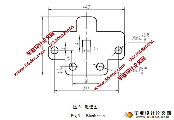
4.1 毛坯形状及尺寸…………………………………………………………………6
4.2 材料利用率计算…………………………………………………………………7
4.3 冲裁力……………………………………………………………………………8
4.4 弯曲力……………………………………………………………………………8
4.5 两处切舌…………………………………………………………………………8
4.6 卸料力、顶件力计算……………………………………………………………9
4.7 计算压力中心……………………………………………………………………9
4.8 公称压力的计算 ………………………………………………………………10
4.9 冲压设备的选择 ………………………………………………………………11
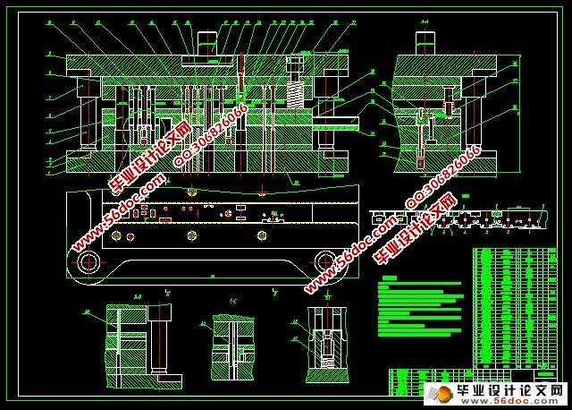
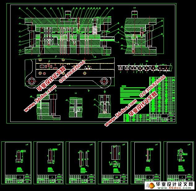
5 模具结构设计 …………………………………………………………………………11
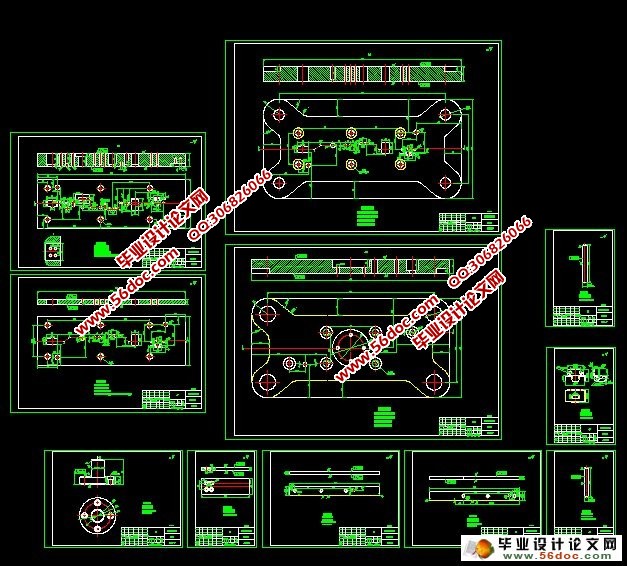
6 主要零部件设计 ………………………………………………………………………12
6.1 冲裁凸凹模刃口尺寸计算 ……………………………………………………12
6.2 弯曲凸凹模尺寸设计计算 ……………………………………………………15
6.3 落料凸凹模刃口尺寸计算 ……………………………………………………16
6.4 其他零件设计 …………………………………………………………………17
6.4.1 定位零件 ………………………………………………………………17
6.4.2 卸料装置 ………………………………………………………………17
6.4.3 模架的选择 ……………………………………………………………18
6.4.4 导向装置 ………………………………………………………………19
6.4.5 上下模座 ………………………………………………………………20
6.4.6 模柄 ……………………………………………………………………20
6.4.7 凸模固定板与垫板 ……………………………………………………21
6.4.8 弹性元件的设计选用 …………………………………………………21
7 凸凹模及冲压设备的校核 ……………………………………………………………22
7.1 凸模的校核 ……………………………………………………………………22
7.2 凹模的校核 ……………………………………………………………………23
7.3 冲压设备校核 …………………………………………………………………23
8 模具装配与调试 ………………………………………………………………………24
9 UG模型的创建与HyperMesh有限元分析……………………………………………24
9.1 UG模型的创建…………………………………………………………………24
9.2 HyperMesh有限元分析 ………………………………………………………26
10 结论……………………………………………………………………………………29
参考文献……………………………………………………………………………………30
致谢…………………………………………………………………………………………30
附录…………………………………………………………………………………………31
|