ЫмМўзЂЩфЙЄвеЗжЮіМАФЃОпЩшМЦ(КЌCADСуМўЭМКЭзАХфЭМ)(бЁЬтЩѓХњБэ,ШЮЮёЪщ,ПЊЬтБЈИц,жаЦкМьВщБэ,ТлЮФЫЕУїЪщ15200зж,CADЭМ8еХ)
еЊ вЊЃКИљОнИјЖЈЫмМўжсЕФГпДчКЭНсЙЙвЊЧѓЃЌЖдЫмМўНјааЙЄвеЕФЗжЮіКЭБШНЯЃЌзюжеЩшМЦГівЛЗљвЛФЃСНЧЛЕФзЂЫмФЃОпЁЃИФЩшМЦДгВњЦЗНсЙЙЙЄвеадЃЌОпЬхФЃОпНсЙЙГіЗЂЃЌЖдФЃОпНсЙЙГіЗЂЃЌЖдФЃОпЕФННзЂЯЕЭГЁЂФЃОпГЩаЭВПЗжЕФНсЙЙЁЂЖЅГіЯЕЭГЁЂРфШДЯЕЭГЁЂзЂЫмЛњЕФбЁдёМАгаЙиЕФаЃКЫЁЂЖМгаЯъЯИЕФЩшМЦЃЌЭЌЪБМђЕЅЕФБржЦСЫФЃОпЕФМгЙЄЙЄвеЁЃећИіЩшМЦЙ§ГЬБэУїИУФЃОпФмЙЛДяЕНДЫЫмМўЫљвЊЧѓЕФМгЙЄЙЄвеЁЃЩшМЦГіРДЕФФЃОпвдТњзуЙЄвЕЩњВњашЧѓЃЌЪЕЯжЫмМўжсЕФИпаЇЁЂздЖЏЛЏЩњВњЁЃ
ЙиМќДЪЃКЫмМўжсЃЛзЂЩфФЃОпЃЛМгЙЄЙЄвеЃЛСуМўЭМ
Analysis of the Injection Process and Design of the Mold Plastics Shaft
Abstract:According to the given plastic shaft size and structural requirements,the technology of plastic parts for analysis and comparison,the final design of an injection mold of a mold with two cavity.The design process from the product structure,the concrete structure of the mold,the mold casting system,mold forming part of the structure ,the roof system,cooling system,the choice of injection molding machine and related parameters of the check,have the detailed design,at the same time,simple preparation of the mold process .The whole design process that the mold can achieve the required pieces of plastic,processing technology.The design of the mold can meet the industrial production requirements, realize the plastic shaft efficient and automated production.
Key Words: Plastic axis; Injection mold; Processing technology; Parts drawing
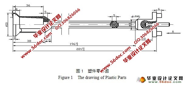
ИУСуМўЪЧвЛИіНЯГЄЕФжсРрЫмМўЃЌзѓВрЪЧвЛИіАМВлЃЌгУЕНВрГщаОЛњЙЙЃЛжаМфВПЗжНиУцЪЧвЛИіЪЎзжжсЃЛгвВрАВЗХЧЖМўЁЃгЩгкЫмМўНЯГЄЃЌзмЬхНсЙЙНЯИДдгЃЌашвЊгУЕНЕФаЭаОЁЂаЭЧЛМгЙЄФбЖШБШНЯДѓЃЌЖјЧвИїВПЗжБкКёВЛЪЧКмОљдШЃЌКмШнвзВњЩњЬюГфВЛзуЕФШБЯнЃЌЮЊДЫашвЊЪЪЕБЬсИпзЂЩфбЙСІКЭзЂЩфЫйЖШЃЌКЯРэЩшЖЈзЂЩфааГЬЃЌНјааГЩаЭЙЄвеЗжЮіЁЃ
ФП ТМ
еЊвЊ…………………………………………………………………………………………1
ЙиМќДЪ………………………………………………………………………………………1
1 ЧАбд………………………………………………………………………………………2
1.1 баОПвтвх…………………………………………………………………………2
1.2 ЙњФкЭтбаОПЯжзД…………………………………………………………………4
1.3 ЗЂеЙЗНЯђ…………………………………………………………………………5
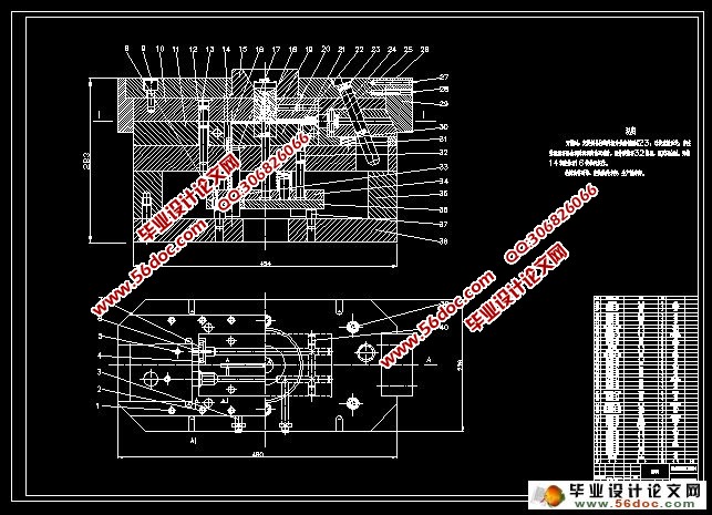
2 ЫмМўЕФЙЄвеЗжЮі…………………………………………………………………………5
2.1 ЫмМўЕФзщГЩЙЄвеЗжЮі……………………………………………………………5
2.2 ЫмМўГЩаЭЙЄвеадЗжЮі……………………………………………………………6
2.2.1 ЫмМўГпДчНсЙЙЗжЮі………………………………………………………6
2.2.2 ЫмМўГпДчОЋЖШЗжЮі………………………………………………………6
2.2.3 БэУцжЪСПЮі………………………………………………………………7
2.2.4 ЭбФЃаБЖШ…………………………………………………………………7
2.3 ЫмМўЕФЬхЛ§жиСП…………………………………………………………………7
2.4 ННзЂЯЕЭГЕФЩшМЦ…………………………………………………………………8
3 аЭЧЛЪ§ЕФШЗЖЈМАННзЂЯЕЭГЕФЩшМЦ………………………………………………………8
3.1 ЗжаЭУцЕФЗжЮі……………………………………………………………………8
3.2 аЭЧЛЪ§ЕФШЗЖЈ…………………………………………………………………10
3.3 ШЗЖЈаЭЧЛЕФХХСаЗНЪН…………………………………………………………10
3.4 ННзЂЯЕЭГЕФЩшМЦ………………………………………………………………10
3.4.1 жїСїЕРЕФЩшМЦ…………………………………………………………10
3.4.2 ЗжСїЕРЕФЩшМЦ…………………………………………………………10
3.4.3 ННПкЕФЩшМЦ…………………………………………………………11
4 ВрЯђЗжаЭгыГщаОЛњЙЙЕФЩшМЦ……………………………………………………12
4.1 аБЕМжљЕФЩшМЦ………………………………………………………………12
4.1.1 аБЕМжљЕФЛљБОаЮЪН……………………………………………………12
4.1.2 аБЕМжљЧуаБНЧЕФбЁдё…………………………………………………13
4.1.3 аБЕМжљГЄЖШЕФМЦЫу……………………………………………………14
4.1.4 аБЕМжљжБОЖЕФМЦЫу……………………………………………………15
4.2 ВрЛЌПщЕФЩшМЦ…………………………………………………………………15
4.3 ЕМЛЌВлЕФЩшМЦ…………………………………………………………………15
4.4 яЦНєПщЕФЩшМЦ…………………………………………………………………16
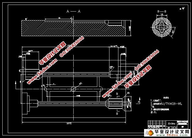
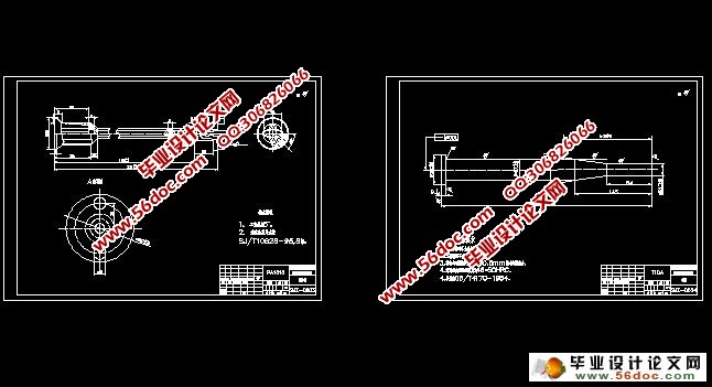
5 ФЃОпГЩаЭСуМўЕФЩшМЦ………………………………………………………………16
5.1 АМФЃНсЙЙаЮЪНЕФбЁдё…………………………………………………………16
5.2 АМФЃМАаЭаОЙЄзїГпДчЕФМЦЫу…………………………………………………16
5.2.1 аЭЧЛКЭаЭаОГпДчМЦЫу…………………………………………………16
6 ЭЦГіЛњЙЙЕФЩшМЦгыМЦЫу……………………………………………………………17
6.1 ЭЦГіЛњЙЙЩшМЦЕФдРэ…………………………………………………………17
6.2 ЭбФЃСІЕФМЦЫу…………………………………………………………………18
6.3 ЭЦИЫжБОЖЕФМЦЫу………………………………………………………………18
7 ЮТЖШЕїНкЯЕЭГ…………………………………………………………………………18
8 зЂЩфЛњгыФЃОпИїВЮЪ§ЕФаЃКЫ…………………………………………………………19
8.1 зЂЩфСПЕФаЃКЫ…………………………………………………………………19
8.2 ЫјФЃСІЕФаЃКЫ…………………………………………………………………19
8.3 АВзАВЮЪ§ЕФаЃКЫ………………………………………………………………19
9 ГЩаЭСуМўМгЙЄЙЄве……………………………………………………………………20
10 НсТл …………………………………………………………………………………21
ВЮПМЮФЯз……………………………………………………………………………………21
жТаЛ…………………………………………………………………………………………22
ИНТМ…………………………………………………………………………………………23
|